
This page of the Cooling Wizard is used to enter and edit the layout of the cooling channels.
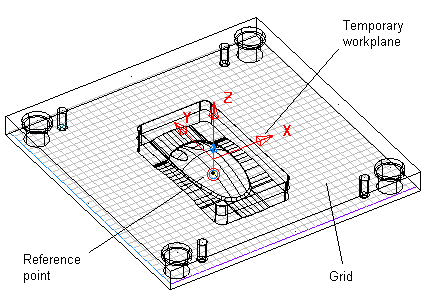
A grid is drawn and fitted within the mold plates representing the plane on which the holes will lie. A temporary workplane is created at the centre of the bounding box around the mold plates to provide a local origin from which the holes are created. A reference point is also drawn. By default, it touches the bottom plane of the bounding box around the mold plate and is directly below the origin of the temporary workplane.
You can view the grid as either ruled or dotted lines by changing the Grid type option on the View page of the Options dialog.
You can also use the following grid controls in the Status bar to alter the grid:
 —
Grid on/off. This draws/undraws the grid.
—
Grid on/off. This draws/undraws the grid.
 —
Grid Scale. This displays the scale of the current grid.
—
Grid Scale. This displays the scale of the current grid.
 — Click to lock the scale of the grid. To unlock the scale, click the
Grid lock
— Click to lock the scale of the grid. To unlock the scale, click the
Grid lock
 button: To increase the scale, zoom out; to decrease the scale, zoom in.
- To re-lock the scale of the grid, click the
Grid lock
button. To set your own grid scale, type a value into the grid scale box. The grid scale is automatically locked to that value.
The Sketch the desired flow of coolant page of the Cooling Wizard is shown below:
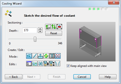
The graphic window in the dialog shows a shaded view of the selected mold plates.
Sectioning
—Use the options in this area to position the plane on which the holes are created. By default, the plane is parallel to the principal plane and lies midway through the bounding box around the selected objects. Use the
Principal plane
buttons
 on the
Status bar to select the plane in which you want to create the holes in the mold plate. Each button displays the label of the axis which is normal to the plane. For example, the button with label Z represents the XY plane. You can move the plane within the bounding box of the mold plate.
on the
Status bar to select the plane in which you want to create the holes in the mold plate. Each button displays the label of the axis which is normal to the plane. For example, the button with label Z represents the XY plane. You can move the plane within the bounding box of the mold plate.
- Depth — This is the depth of the plane. It is measured from the reference point.
 - The slider changes the depth of the plane. If you move the slider, the plane moves through the mold plate. If you move the reference point along the principal axis, the values at the end of the slider change. The values on the slider are the minimum and maximum depths that the plane can move in the mold plate and are measured from the reference point.
 —
Move plane to point. Click this button and then input a position. The plane will move to that position. You can use the temporary workplane to create holes from particular points on the plane.
—
Move plane to point. Click this button and then input a position. The plane will move to that position. You can use the temporary workplane to create holes from particular points on the plane.
 —
Reverse plane normal.
Click this button to reverse the direction of creation of the baffle.
—
Reverse plane normal.
Click this button to reverse the direction of creation of the baffle.
 —
Move reference point. Click this button and then click a point within the selected mold components. This also moves the origin of the temporary workplane so that it is aligned with the reference point. You can move the point to a critical area and use it to measure the distance of the plane from that area.
—
Move reference point. Click this button and then click a point within the selected mold components. This also moves the origin of the temporary workplane so that it is aligned with the reference point. You can move the point to a critical area and use it to measure the distance of the plane from that area.
- Reset — This resets the reference point, the temporary workplane and the plane back to their default positions.
Create / Edit — The buttons in this section are used for creating and editing layout piece lines, and editing holes:
- Mode:
 — Click this button to
Create continuous lines on the mold plate. Continuous lines are ones where the end of the last line becomes the start of the next.
— Click this button to
Create continuous lines on the mold plate. Continuous lines are ones where the end of the last line becomes the start of the next.
 — Click this button to
Create single lines. These lines are created between two distinct positions.
— Click this button to
Create single lines. These lines are created between two distinct positions.
 — Click this button to
Create baffle layout.
— Click this button to
Create baffle layout.
 — Click the
Edit layout button to edit the layout of the lines.
— Click the
Edit layout button to edit the layout of the lines.
 — Click the
Edit holes button to edit the cooling holes.
— Click the
Edit holes button to edit the cooling holes.
 — Click this button to toggle
Snap to grid on and off.
— Click this button to toggle
Snap to grid on and off.
- Edits:
 — Click the
Edit modify button to display the editing dialog.
— Click the
Edit modify button to display the editing dialog.
 — Click the Reverse button to reverse selected items
 — Click the Edit
button to display the
Edit tab.
— Click the Edit
button to display the
Edit tab.
 — Click to change selected hole to a
Through hole.
— Click to change selected hole to a
Through hole.
 — Click to change selected hole to a
Non-through hole.
— Click to change selected hole to a
Non-through hole.
 — Click the
Show outline button to toggle the display of hole outlines on and off.
— Click the
Show outline button to toggle the display of hole outlines on and off.
Keep aligned with main view — Select this option to keep the view in the wizard in the same orientation as the view in the graphics window. As you change the view in the graphics window, the view in the wizard changes too. You cannot change the view in the wizard. Deselect this option to change the orientation of the view of the graphics window, but not the view in the wizard. You can independently change the view in the wizard by zooming and panning.
Next — Takes you to the Error checking page of the wizard.