
This page lets you modify the Constraint Plane and select the directions to remain unaltered by scaling.
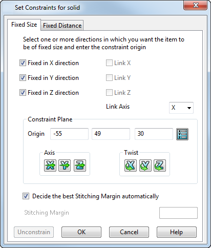
Use the check boxes to select the directions to remain unaltered by scaling.
Fixed in X direction — Constrain the item so that it is of fixed size in the X direction with respect to the constraint workplane.
Fixed in Y direction — Constrain the item so that it is of fixed size in the Y direction with respect to the constraint workplane.
Fixed in Z direction — Constrain the item so that it is of fixed size in the Z direction with respect to the constraint workplane.
Use the Link Axis and Link options to create linked scaling constraints. For example, link the X and Y dimensions as follows:
- Deselect Fixed in X direction.
- Select Link X.
- Select Y axis from the Link Axis drop-down list. This links X and Y dimensions so any change you make to the Y dimension are also applied to the X dimension.
- Use Edit tab > Transform panel > Scale to scale the solid. The scaling constraints that you set are applied and a confirmation message is displayed.
Constraint Plane
When you scale the constrained object, it is the constraint plane origin that is scaled. The constraint plane origin moves with the scaled origin and the constrained entity repositions itself around the updated constraint plane origin.
The default origin of the constraining entity is displayed on the model. Change the Origin, Axis and Twist options to modify the constraint plane
- Origin — The X, Y, Z coordinates of the centre point of the constraining entity. If you need to alter the origin, enter the new coordinates in the relevant box.
 — Display the
Position dialog so that you can define the constraint plane.
— Display the
Position dialog so that you can define the constraint plane.
- Axis — To change the direction of the constraint plane's axes, click the button of the axis you wish to change. This displays the Direction dialog. Use this dialog to input the axis information and click Accept.
- Twist — To twist the constraint plane about its axis, click the button of the axis you wish to twist. This displays the Calculator dialog. Use this dialog to input the twist value and click Accept.
Decide the best Stitching Margin automatically — If you want to keep the user-defined feature the same size, scaling produces a gap around the feature. A stitch margin stretches the portions of the solid around the user-defined feature to blend the gap generated around the feature and maintain the closure of the solid.
Select this option to base the size of the stitching margin on the size of the gap created.
Deselect this option to use the Stitching Margin option:
Stitching Margin — Enter the distance around the periphery of the item being constrained, where stretching would occur when you scale the item. This option is only available if Decide the best Stitching Margin automatically is deselected.
The following shows the effects of using the automatically calculated stitch margin and using different sizes of user-defined stitch margins.
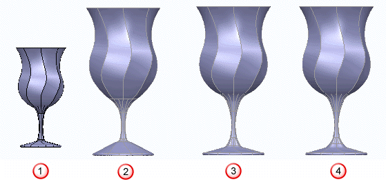
 — Original.
 — Stitching margin decided automatically.
 — User-defined stitching margin of 5.
 — User-defined stitching margin of 10.
Unconstrain — Remove all the constraints on the selected item and close the dialog.
OK — Accept the constraints settings and close the dialog.