
Use the Vector tab of the Position dialog to measure a vector between two points and use it to define a position. The offsets, angles, length, and elevation between the two points are displayed.
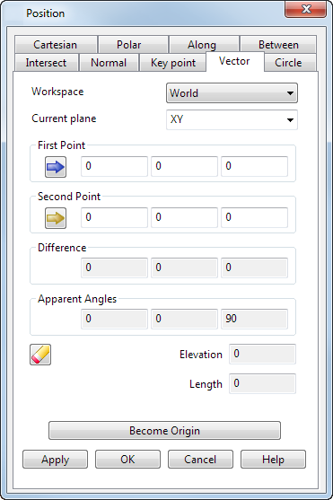
Workspace — Select the workspace you are working in. The available options are:
- Relative — The position being defined is relative to another position which becomes the origin of the workspace. The positions are aligned with the active workplane or the global workspace if no workplane is active.
Relative mode is not always available since there may not be a suitable relative co-ordinate. In this case, select a suitable position (such as the intersection of two lines) and make it the origin of a relative workspace with the Become Originoption.
- Workplane — The position being defined is relative to the active workplane if one exists.
- World — The position being defined is relative to the global coordinate system.Note: If any items are locked, the locks are discarded when you select a different workspace.
Current plane — Use this drop-down list to select one of the three principal planes. The current plane is relative to the selected Workspace option.
You must have a starting position from which the new position is entered.
- First Point — Enter the first point of the vector or click on a point on the model to enter its coordinates. This point is displayed in pink on the screen (using the default colour scheme).
- Second Point — Enter the second point of the vector or click on a point on the model to enter its coordinates. This point is displayed in red on the screen (using the default colour scheme).
When you click OK or Apply, a new position is entered by going along the vector from the start position.
- Information from the two positions of the vector is displayed automatically in the boxes for the following options:
Difference — These are the differences in the X, Y, and Z values of the first and second points of the vector.
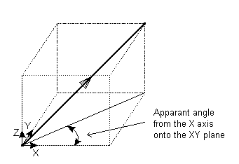
Apparent Angles — The apparent angle is measured between the projection of the vector onto a plane and the selected axis. If the axis is X, the plane is XY. For Y the plane is YZ and for Z it is ZX. An example is shown below of the apparent angle for the X axis:
 Reset — Click this button to reset the values on the page.
Length — This is the true length (in 3D) between the points.
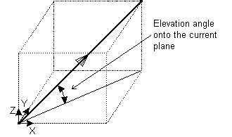
Elevation — This is the elevation angle of the new vector from the current plane.
Become origin — Click this button to position the origin at the coordinates specified in the dialog. Any relative coordinates are measured from this origin.
Apply — Inputs the position. If the current operation allows multiple points, the dialog remains displayed ready for you to enter more points. Otherwise, the dialog is closed.
OK — Inputs the position and closes the dialog.
Cancel — Aborts the position entry.