
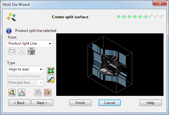
A split surface is created automatically using the default settings. Use the Create split surface page to change the split surface settings:
 — This indicates the curve that is currently selected to be used to generate the split surface.
From
 — Use the product split line to generate the split surface. The
Alternative Compcurve option lets you
select an alternative composite curve from which to generate the split surface.
— Use the product split line to generate the split surface. The
Alternative Compcurve option lets you
select an alternative composite curve from which to generate the split surface.
 — If
Alternative Compcurve is selected from the drop down, this option is used to create an alternative curve to use when generating the split surface. This means that you can create a partial split surface and then use the wizard to generate the remaining portion. Selecting this option automatically hides the block and the product to make it easier to trace the curve.
— If
Alternative Compcurve is selected from the drop down, this option is used to create an alternative curve to use when generating the split surface. This means that you can create a partial split surface and then use the wizard to generate the remaining portion. Selecting this option automatically hides the block and the product to make it easier to trace the curve.
The alternative composite curve should surround the partial split surface and the product.
 — The
Delete button now deletes all composite curves created on this page. If one of the curves is currently selected, then it is also deleted and the wizard defaults to the product split line.
— The
Delete button now deletes all composite curves created on this page. If one of the curves is currently selected, then it is also deleted and the wizard defaults to the product split line.
Type
 — The options on this drop-down list define the split direction.
Orthogonal direction — Affects the direction of laterals of the split surface.
 — Advanced split surface options. The
Split Segments dialog is displayed.
— Advanced split surface options. The
Split Segments dialog is displayed.
 — Create one or two stepped split surfaces. When you select this button, the
Stepped Split Surface dialog for a core (Core
Stepped Split Surfaces) or cavity (Cavity Stepped Split Surface) is displayed.
— Create one or two stepped split surfaces. When you select this button, the
Stepped Split Surface dialog for a core (Core
Stepped Split Surfaces) or cavity (Cavity Stepped Split Surface) is displayed.
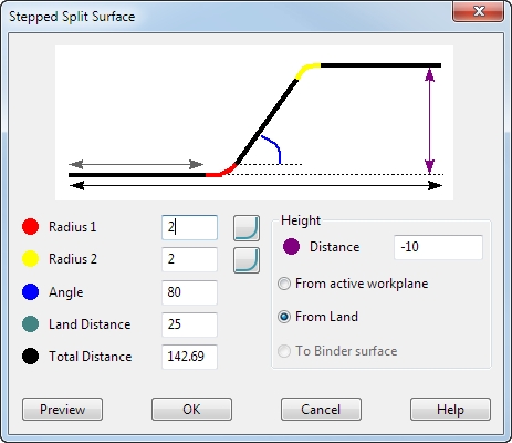
OK — A stepped split surface is created and a Query dialog is displayed:
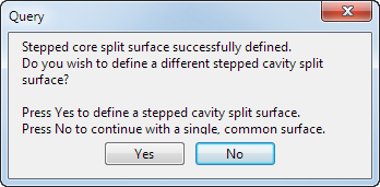
Yes — The stepped split surface form is displayed again and the user can create a second surface for the cavity insert.
No — Use the surface that has been created as the common surface.
If you create two stepped surfaces within the Mold Die Wizard and exit the wizard without splitting the mold, the two surfaces are output as solids.
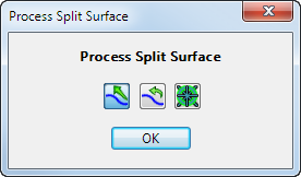
 —
Process Split Surface. Click this to display the
Process Split Surface dialog.
—
Process Split Surface. Click this to display the
Process Split Surface dialog.
 —
Retain tangents. Select this to retain the tangency of the projected curve across the split surface.
—
Retain tangents. Select this to retain the tangency of the projected curve across the split surface.
 —
Smooth surface. Attempt to smooth the split surface by adjusting the tangent direction of the projected curve.
—
Smooth surface. Attempt to smooth the split surface by adjusting the tangent direction of the projected curve.
 — Preserve symmetry. Selecting this option preserves the symmetry of the split surface when
Align to Axes has been selected from the
Type drop down list.
— Preserve symmetry. Selecting this option preserves the symmetry of the split surface when
Align to Axes has been selected from the
Type drop down list.
 —
Create angled split surface. This displays the new
Angle Options dialog.
—
Create angled split surface. This displays the new
Angle Options dialog.
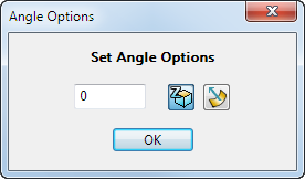
 — Enter the required taper angle in the text box.
 — Create split surface in principal plane.
Note: You can access the principal plane options on the status bar of the PowerShape window. You can use these options to select a different plane and then create a vertical split surface by using the Angle Options or the advanced split surface option.
 — Create split surface normal to underlying surface.
 — Generate the split surface.
 — Reset the graphic in the wizard graphic window back to the original view.
Next — Displays the Define block heights page of the Mold Die Wizard.