
Select the Stresses tab in the Bar Value Selection dialog to define stress values for presentation.
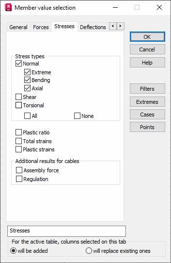
You can select the following stress types for presentation.
- Normal - adds a table column to display normal stresses (perpendicular to the bar cross section) obtained during structure analysis.
- Extreme - adds a table column to display min/max stresses being the sum of axial and bending stresses, obtained during structure analysis.
- Bending - adds a table column to display bending stresses (resulting from the bending moment: My*Vz / Iz or Mz*Vy / Iy) obtained during structure analysis.
- Axial - adds a table column to display axial stresses (resulting from the longitudinal force N / A) obtained during structure analysis.
- Shear - adds a table column to display shear stresses obtained during structure analysis. Stresses are calculated by dividing a value of the transverse force by the shear area: Fy / Wy or Fz / Wz.
- Torsional - adds a table column to display torsional stresses obtained during structure analysis. Stresses are calculated by dividing a value of the torsional moment by the section modulus for calculation of torsion stresses Mx / Wx.
Normal stresses are a sum of stresses resulting from axial force and bending. Extreme normal stresses are found at certain characteristic points of a cross section. The location of these points depends on the section shape, such as corners of flanges, a point on the perimeter of a round-section tube, and so on.
If the cross-section has a determined type of shape:
- it comes from standard section databases,
- it is defined by means of parameters in dialog boxes,
- it is geometrically defined in Section Design and saved to the database selecting the type,
then characteristic points for calculation of stresses can be specified correctly (blue points in the drawing).
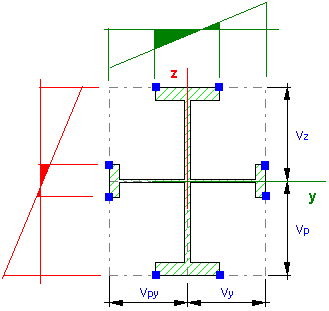
If the cross-section is not a determined type of shape:
- by means of values of physical properties (Ax, Iy, Iz...)
- in the Section Design module and saved to the database without selecting the type,
then stresses are calculated at characteristic points of the section, located in corners of the contour defined by the distances Vy, Vz. It may lead to overrated values of stresses at a point outside the section (blue points in the drawing).
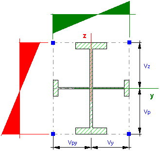
For exact analysis of stresses in this type of a bar section, select Results > Stress Analysis > Stress Analysis - Bars.
After selecting the Plastic ratio option, an additional table column will show values of this ratio:
- Beginning of the plasticity state - Value of the plastic ratio equals 0.0
- Full plasticity of a section - Value of the plastic ratio equals 1.0
- Value of the plastic ratio greater than the defined value (greater than zero and less than 1.0).
Additional results for cables selects either assembly force or regulation for cable structures.
Assembly force is calculated when the initial stress of a cable element is defined by means of its length, (absolute or relative shortening of a cable). It is calculated as an internal force which does not cause displacement of the cable ends for the assembling case (shortening of the cable is considered).
Regulation is calculated when the initial stress of a cable element is defined by means of a determined prestressing force or stress. It is calculated as required shortening of the cable which results in the determined stress for the assembling case.
The Extremes field contains the following options.
- Detailed information - The table will contain values of the respective stresses, numbers of the bar, and case for which the stresses have been calculated.
- Envelope with concomitants - the table will contain the min/max and other stress components which have been calculated in the points with the maximum stress component value.
- Extreme combinations - the table will contain the definition of the combination for which the min/max value has been obtained.
The field also contains the Local and Global options. Selecting the Global option has the same result as going to the Global extremes tab in the table. Two values are obtained (minimum and maximum) for the entire structure. While the Local option results in the operation of finding extremes for each point on a bar according to all load cases. Extremes of each load case may be located in different points. Disabling both options finds the extremes for each point of every bar according to every case (two values MIN and MAX for each bar).