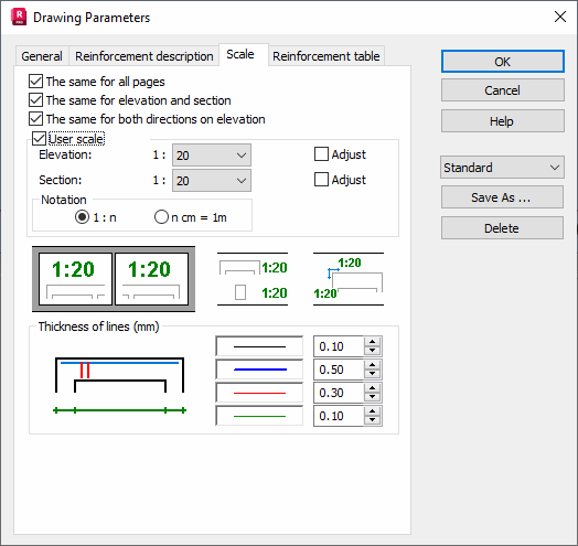
Select Analysis > Drawing or click ![]() (Drawing parameters) and then select the Scale tab.
(Drawing parameters) and then select the Scale tab.

The Scale dialog options are described as follows.
Same for all pages. The scale for the drawing of one element is imposed on all pages. For example, in the case of a beam comprising several spans each is presented on a separate page, identical scaling for all pages that contain an instance of the selected beam.
Same for elevation and section. An element section and its view are drawn in an identical scale
Same for both directions on elevation. Maintains the aspect ratio of the element when scaled.
User scale. You can set your own scale of views and sections before their generation. The following options become accessible when enabled.
- Elevation: scales elevation views.
- Section: scales cross-section views.
- Adjust: scale is adjusted to the dimensions of a view and an object in both elevation and cross-section.
- Notation 1:n: a defined scale ratio expressed in standard notation
- Notation n cm = 1 m: Relational scale definition. For example, the number of centimeters in a drawing represent 1 m in an object.
Line thickness may also be selected for:
- Element elevation and section contour,
- Main reinforcement,
- Transversal reinforcement,
- Dimension lines.
These settings allow fitting a final drawing to your needs and printer capabilities.
