During the design of an RC column subjected to compression and bending the program checks independently the three cross-sections along the column height: upper, lower and positioned in the central part (the exact position of this cross-section is determined by the central moment according to guidelines of individual codes).
Depending on the code recommendations, the cross-section position as well as that whether it is a sway or non-sway column determines if second order effects are taken into account in a given cross-section (obviously, if the column slenderness exceeds the code-specified limit value).
The most-often adopted procedure for the majority of RC codes is as follows:
- for structures with non-sway nodes - the influence of slenderness can be taken into account in the central cross-section of a column; for cross-sections at the column ends the influence of slenderness is ignored
- for structures with sway nodes - the influence of slenderness is taken into account identically for each column cross-section.
The exception includes e.g. the UK BS code according to which the influence of slenderness is taken into account also at ends of a column with non-sway nodes. However, ACI and CSA codes allow for additional increase of the influence of slenderness for the central cross-section for a structure with sway nodes.
For thus-understood three cross-sections calculations of reinforcement are performed. Reinforcement is calculated in the iterative process; a number of iterations is increased until the program adopts the reinforcement which ensures that the capacity condition is satisfied in all three column cross-sections for each of the combinations.
A design combination is understood as a pair composed of a set of load combinations and the cross-section position for which the greatest ratio is achieved.
Three sets of forces (i.e. an axial force, moments and, if needed, lateral forces) for each combination in the load definition table correspond to the three cross-sections that undergo the design process.
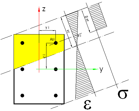
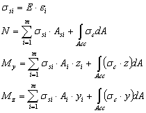
The calculation of the column capacity for biaxial bending proceeds according to the following procedure:


where: Acc is the area of the compression part (according to the diagram of the s distribution), E denotes Young's modulus.
The drawing illustrates the rectangular stress diagram. For some codes the diagram is parabolic-rectangular.
The exception includes the code-specified method available for the Polish code PN-B-03264 (2002).
Increasing the reinforcement until the required capacity is reached (the optimization algorithm) proceeds according to the following procedure:
- at each iteration step the program checks which of the methods of increasing the area is more efficient
- the greatest diameter of reinforcing bars of a selected group is adopted (groups of corner bars and bars distributed along the sides are considered independently)
- a number of bars along the column sides is increased
- a number of bars in a group (bar bundle) is increased - groups of corner bars and bars distributed along the sides are considered separately
- a solution that allows achieving the greatest possible capacity with the least possible increase of the reinforcement mass passes to the next step
- the capacity for all load combinations is checked one by one by the program; if for any of the combinations the capacity condition is not satisfied, the next iteration step takes place (the increase of reinforcement)
- an increase of the optimization level enables parallel analysis of several scenarios of the increase of the reinforcement area; finally, the most optimal solution is chosen.
