
Open the Arc dialog using either of the following methods:
- Click Geometry menu > Objects > Arc.
- Click
 .
.
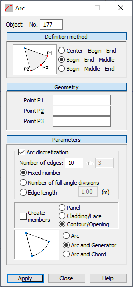
The dialog, which lets you define an arc, has the following parts:
- Object displays the number of the created or selected object
- Definition Method
- Geometry
- Parameters.
When the Arc dialog is fully opened, clicking Definition Method, Geometry, or Parameters minimizes the corresponding part of the dialog so it displays only the options used at a given time. When the window is minimized, clicking one of the button extends the dialog.
Definition Method
Under Definition Method, options for defining an arc are based on defining three points. Schematic drawings of the arc defining method are shown below.

|
The arc is defined using the center and two points on the arc (beginning and end). |

|
The arc is defined using three points on the arc (beginning, end, and middle). |

|
The arc is defined using three points on the arc (beginning, end, and end). |
Geometry
Coordinates for points P1, P2 and P3 can be entered in the corresponding fields under Geometry. The significance of these points depends on the method used to create the arc.
Parameters
Additional options that let you select the method of dividing the arc into elements are located in the Parameters part of the dialog box.
If Arc discretization is turned off, an arc is created using the analytical method.
When the Arc discretization is selected, you can define the parameters for dividing an arc:
- Fixed number when selected, divides the arc into the number of elements defined in Edges.
- Number of full angle divisions when selected, the number in Edges specifies the number of full angle (360 degrees) divisions. When Min becomes active, it defines the fewest number of full angle divisions (default is 3). An arc is always divided into equal segments. Sometimes, the number of full angle divisions does not divide the arc into equal segments. In this case, Robot automatically finds the number of arc divisions that divide the arc into equal segments.
- Edge length when selected, denotes the lengths of the sides of the polygon approximating the arc (the polygon inscribed into the arc).
Create Members option is available only when Arc discretization is selected.
When selected, the arc is made up of member elements (individual parts of the arc are members).
When Create members is turned off, the following options become available:
- Panel - When selected, the arc is defined as a panel with default parameters: reinforcement type and thickness.
- Cladding / Face - When selected, the arc is defined as a face without the default properties such as reinforcement type and thickness, but with specified cladding parameters. You can use this object in two ways:
- When creating a volumetric structure (solid), it can be a face of a volumetric object
- When distributing planar loads onto members, the cladding attribute determines the method and direction of load distribution. Arbitrary loads (planar, linear and point loads) can be applied to a cladding, a next transferred onto members
- Contour / Opening - When active, the arc is defined only as a contour that has neither panel nor cladding properties. If a contour is inside a panel or another contour, an opening is created. Such contour is assigned the following:
- Thickness, the contour is a panel
- Cladding, the contour is a face.
To define an arc:
- Select an arc definition method.
- Define the coordinates of the characteristic points on the arc:
- Using text: Enter the coordinates for the individual points in the dialog under Geometry and click Apply.
- Graphically: Click in P1 under Geometry, and switch to the graphic layout. Click on the point representing the first point on the arc, then click on the points representing P2 and P3.
- Method combining the graphic definition and the definition using text
- Define the division parameters for the arc (the number of divisions in the appropriate directions).