
Use the new global option in Structural Settings to create steel element geometry starting from the exact start and end click point.
 Structural Settings panel
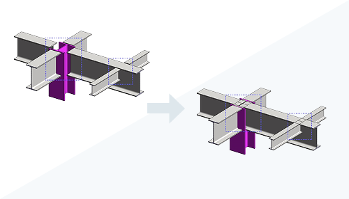
 (Structural Settings) Structural Steel Elements tab Automatic Shortening Disable automatic shortening of steel elements during auto-join.

- Point-to-point modeling defines precise geometry allowing you to visually check the correctness of steel elements.
- The new global option will also retroactively change the geometry of all steel elements of the existing project.
- Point-to-point modeling doesn't change auto-join behavior.
- Structural Steel Framing
- Structural Steel Columns
- Structural Steel Truss
- Beam systems using Steel sections
- Bracings using Steel elements
The Length parameter was moved to the Dimensions category in the Properties palette and renamed to System Length to better reflect that this is the analytical length, the theoretical distance between the two points used to create the member. The length of the physical element will continue to be displayed with the Cut Length parameter which takes into account any geometry changes to the member length.
This change is valid for all structural members.
Slanted Column Behavior and Workflow
This workflow update enhances the reliability of parameters.
When you add a slanted column using the point-to-point workflow, the column's geometry now extends to the end point of the system length.
If you turn off the point-to-point option, the slanted column will adjust to a secondary state. In this state, the column aligns with the bottom of the intersecting beam and attaches to the smallest intersection line. This differs from the default behavior that trims the face tangent to the beam.
For additional information, see Point to Point Steel Modeling.