
8.4 Defining a Grillage with a DXF File
Subjects Covered
- Preparing DXF files for Autodesk Structural Bridge Design grillages
- Importing DXF files into Autodesk Structural Bridge Design to define grillages
Outline
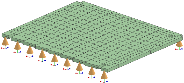
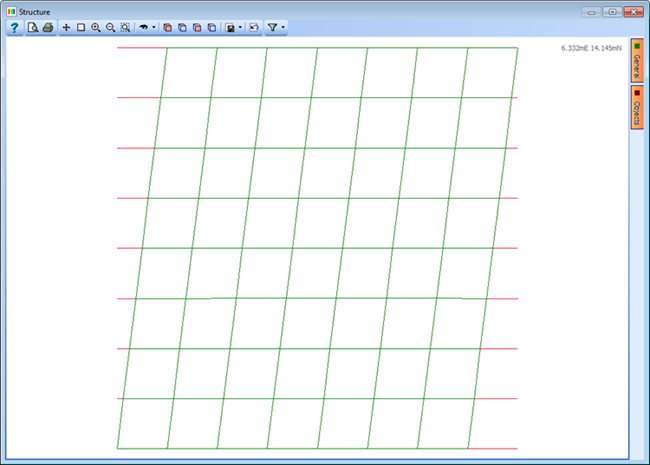
The grillage for the skew deck structure below would be easy to define directly in Autodesk Structural Bridge Design. However, in this example an alternative method for defining such geometry in Autodesk® AutoCAD is outlined. A DXF file has been prepared in AutoCAD using a set of specialised commands which are loaded into AutoCAD.
Below is the drawing containing the geometric data for the grillage beam elements. Note that for a grillage Autodesk Structural Bridge Design will only recognise elements defined using line or polyline entities in the DXF file, and these will be interpreted as beam elements when data from the DXF file is imported into the program.

The process of creating a grillage is very simple in AutoCAD; the basic process is defined below.
Creating a DXF File for a Grillage using a CAD Application
Open Autodesk® AutoCAD.
Set the drawing limits and set the viewing angle as a plan view.
Draw a single line representing one longitudinal beam in the grillage.
Use the 'Array' or 'Multiple copy' tool to create an array of longitudinal beams.
Repeat these two steps to create a set of transverse beams.
Note: It is not necessary to split the beams into individual beam elements as this can be done automatically during the import.Save as a DXF file.
Save the DWG file and close AutoCAD.
Importing the DXF File into Autodesk Structural Bridge Design to Create a Grillage
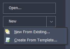
Start the program and select the New drop down button item Create From Template and pick the “EU Project” template.
In the main menu select File | Titles to set the Project Title as “Create Grillage from CAD file” with a sub-title of “Example 8.4” and a Job Number of “8.4”. Also add your initials to the Calculated by data item.
Click on ✓ OK to close the Titles form.
Click on Add Model | Refined Model in the toolbar at the top of the Structure Definition pane.
With the "Refined Model" node selected in the Structure Definition navigation window, click on the Import Model
 icon in the toolbar to open the Import Model form.
Select the “Bridge Structure” radio button. This will ensure that all members in the Z=0.0 plane are automatically assigned as deck members when the data is imported into the program.
Click on the Browse button and open the supplied DXF file with a name of “grillage.dxf”.
Click on the Next button to move to the next form.
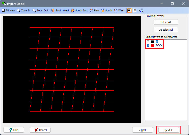
Untick the tick box for layer “0” so that only the tick box for layer “DECK” is ticked.
Tick the tick box for “Split intersecting beam elements” so that both available tick boxes are ticked. Ensure that the One linear drawing unit... field is set to “metre”. This will ensure that the grillage is split into individual beam elements and that the grillage will be at the correct scale.
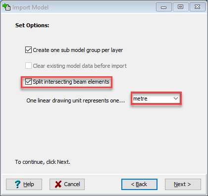
Click on the Next button to move to the next form.
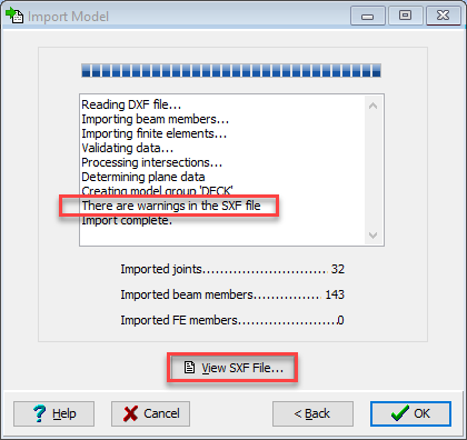
The progress of the import is logged and the warning message should be noted. To inspect the meaning of these warnings click on the View SXF File... button. These are related to the end joints of the longitudinal beams where they are only connected to a single member. These members will be deleted later so we can move on.
Click ✓ OK to close the Import Model form.
The Member Details form will open automatically. Note that the tick boxes in the Deck column are ticked automatically, indicating that the imported beam elements are in the deck. Hence, these beam elements will be considered as deck members in the calculation of influence surfaces and the application of loads.
Delete the 8 members at each end of the structure that are not required (highlighted in red below) by selecting them in the graphics window (use the
Ctrlkey for multiple selection) and then theDeletekey or - button.Click ✓ OK to close the Member Details form.
Individual beam elements in the longitudinal direction would need to be grouped together as being in longitudinal beams to enable various grillage functions in the analysis.
To set up the longitudinal and transverse members first define Span End Lines by clicking on the Refined Model node at the top of the navigation window and then using the + toolbar button to select Span End Lines.
Define the two lines graphically by clicking on the two ends of the leftmost edge and then the two ends of the rightmost edge.
Close the Span End Lines form with the ✓ OK button.
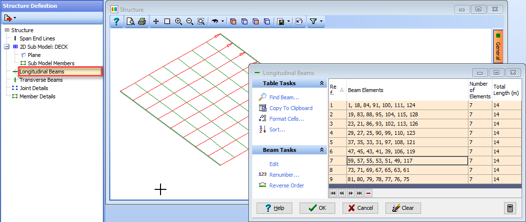
Select the Longitudinal Beams object in the navigation tree to open up the Longitudinal Beams form.
Simply window round the entire structure and the software will determine contiguously connected beams between span end lines to create 9 individual longitudinal beams.
Use ✓ OK to close the Longitudinal Beams form.
Select the Transverse Beam object in the navigation tree to open the Transverse Beams form and then window round the entire structure. Again the software determines contiguously connected beams between the two extreme longitudinal beams to create 8 individual transverse beams.
Use ✓ OK to close the Transverse Beams form.
Additional data for the Design Lines, Carriageways and Section Properties etc. can be defined to complete the structure file. See examples 6.4 and 10.1 for information on defining grillage structure files.
The structure file can be saved at this point by using the main menu File | Save as, and saving the file with a name of “My EU Example 8_4.sst”.
Summary
This method enables users to import data from a DXF file to define a beam element grillage. Such a method of working can be useful when the complex geometry of a bridge deck has been defined in a drawing file. It is worth noting that design lines can be imported from DXF files by using the “Import” button on the Define Design Line form, which is a great help when trying to create a curved structure and carriageway that follows a transition curve defined in a CAD program.