
8.3 Using a Section Library to Create a PS Beam with a Psuedo Curved Soffit
Subjects Covered
- Importing DXF sections
- User defined library shapes
- User defined SXF files
- Design sections from Design beams
Outline
This example demonstrates the DXF interface with Autodesk® AutoCAD and similar programs as well as the use of Structural Bridge Design section libraries and the use of the SXF format interface files. It also demonstrates the process of creating Design sections from Design Beams as specific locations.
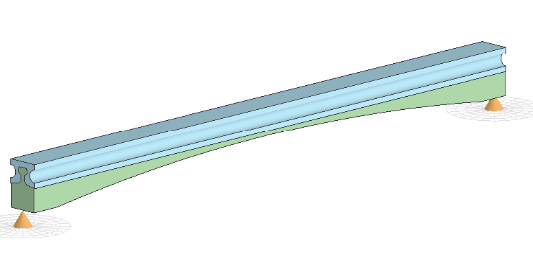
The objective of the example is to create a pre-tensioned pre-stressed beam that represents one with a curved soffit, although the tendons remain horizontal throughout. The actual prestressed beam with the insitu slab infill looks like:
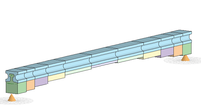
In Autodesk Structural Bridge Design it is not possible to create a prestressed beam with an actual curved soffit, but it is possible to represent it as a beam with variable section in a stepped fashion.
The section elements at the end of the beam are imported from CAD files and a reinforced beam is created using these section components where a curved soffit can be applied. To enable this the section shapes are placed into a section library and the tendons exported into an ASCII file.
By defining specific points of interest on this RC beam that relate to the points where we want to define the individual segments of the PS beam, we can extract the sections at these locations and by putting these into a section library they can easily be used in the definition of the PS beam.
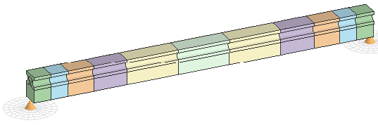
The final pseudo curved prestressed beam should look like:
The sections and crosses representing the tendons were created in AutoCAD using standard drawing elements such as straight lines and polylines. Note that the section outline has to have a closed perimeter in order for it to be imported into Autodesk Structural Bridge Design.
Procedure
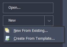
Start the program and select the New drop down button item Create From Template and pick the “EU Project” template.
Use the menu item File | Titles... to set the title as “PS Beam with Curved Soffit” with a sub-title of "Example 8.3". Also add your initials to the Calculated by data item. Click on OK to close the Titles form.
Set the navigation window to Design Sections and use the Import icon
 on the toolbar to import the CAD section from “M2 Beam modified.dxf”. The section and tendon were drawn in two layers in metres so import both of these.
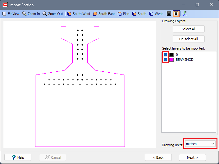
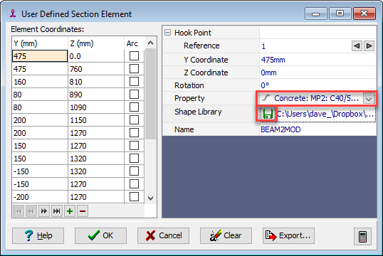
The navigation window shows a new section called “M2 Beam Modified” (from the CAD file name) with a section element called “BEAM2MOD” (from the drawing layer name) and a set of tendons.
Select the section element "SE1" and in the resulting form set the material Property to the "C40/50" concrete. Also add the shape to a user defined section shape library file by clicking on the Shape Library icon. Create a new library called "My EU Example 8_3 shape.lib". Use the ✓ OK button to close the User Defined Section Element form.
With the “SS1” section selected in the navigation tree click on the Import icon
in the toolbar again and this time select the DXF file "Infill Slab.dxf". This has been drawn in a layer called INFILLSLAB, so ensure this layer has been selected before clicking on Next >.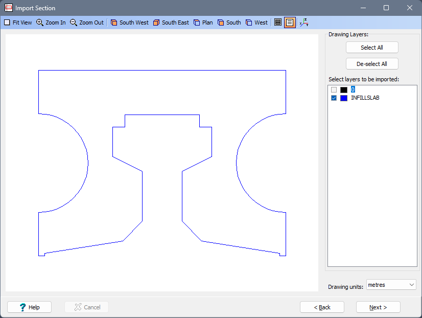
Select the section element "SE2" in the navigation tree and in the resulting form set the material Property to the “C32/40” concrete. Also add the shape to the user defined section shape library file by clicking on the Shape Library icon and selecting the same library file as before. Use the ✓ OK button to close the User Defined Section Element form.
Select Tendons in the navigation tree to open up the Define Tendons form. Export these tendons into an ASCI text file in an “sxf” format using the Data Export button at the bottom of the form. Save this to a file called “My EU Example 8_3 tendons.sxf” and close the Define Tendons form with the ✓ OK button
The shapes we have saved in the shape library are now going to be used to define the shape of an RC beam.
Change the navigation window to Design Beams and use the
 icon in the toolbar to create a New Reinforced Concrete beam.
The beam length will remain at “20m” but in the Define field select “Section” to open the RC Beam Section Definition form.
Click the table insert + button, and select “User Library” from the new row component list and open the file “My EU Example 8_3 shape.lib” which will display all the stored shapes in the library. Select the shape “BEAM2MOD” and then close the User Defined Component form with the ✓ OK button.
Change the Property for this component to the “C40/50” concrete and then click twice on the bottom edge of the shape in the graphics window, to define this as the soffit (turns thick red), before closing the RC Beam Section Definition form with the ✓ OK button.
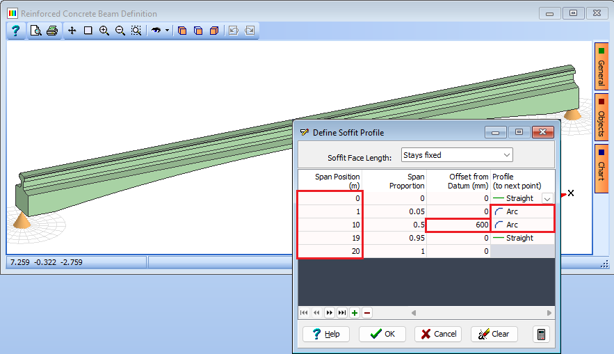
In the Define field of the Beam Definition form select “Soffit Profile” to open the Define Soffit Profile form. Three addition points need to be added to this table (using + button), with the centre one given an offset of 600mm, and segments 2 and 3 are marked as “Arc”, as shown here:
Close the Define Soffit Profile form and the Beam Definition form using the ✓ OK button.
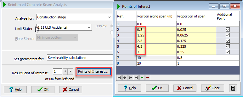
It is now necessary to define “Points Of Interest” at specific locations were we wish to establish the section shapes for input into out Prestressed beam. This is done from the beam analysis form.
Right mouse click in the navigation window and select “Analyse Beam...”. In the Beam Analysis form click on the Points of Interest button and add points at 0.5m 1.5m 2.75m 4.5m 7.0m.
Close the Points of Interest and Beam Analysis forms with the ✓ OK button.
Right mouse click in the navigation window and select “Create Design Sections...” to open the Design Section Creation form. Select all but the first and last points by ticking the Creation Point tick boxes.
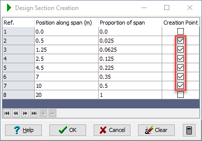
Close the Design Section Creation form with the ok button and automatically the navigation window changes to Design Sections and the six new sections are displayed.
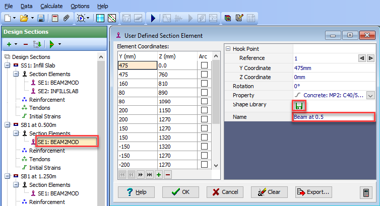
For each of the new sections we need to change the single shape name to indicate the location and save each one into the shape library defined earlier.
Click on the section element “SE1” for the first new section “SB1 at 0.500” to open the User Defined Section Element form. This will enable the Name to be changed to “Beam at 0.5” before clicking on the Shape Library icon to add this shape to the same library file as before.
This should be repeated for the other 5 sections.
When all 6 sections have been saved in the section library then they are available to be used in the definition of the Prestressed beam
Change the navigation window to Design Beams and create a New Pretensioned Prestressed beam that has a 20m spam and is a uniform section (for the moment).
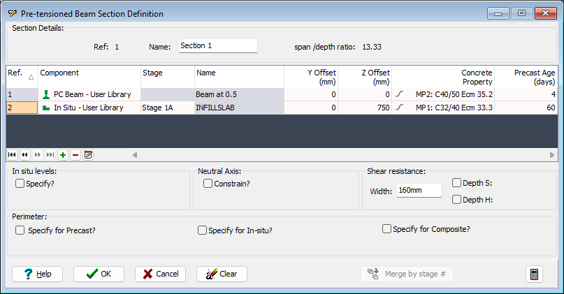
In the Define field select “Section” to open the Pre-tensioned Beam Section Definition form. Click the table insert + button, select “PC Beam - User Library” from the new row component list, and select the library file that has been used throughout this example. Select “Beam at 0.5” from the available shapes and close the Select Shape form with ✓ OK. The Concrete Property should be set to the grade C40/50 concrete.
Click the table insert + button and select “In Situ – User Library”, and open the same library file, picking the “INFILLSLAB” shape before closing the Select Shape form with ✓ OK.
In the Define field of the Beam Definition form select “Tendons” which will open the Tendon Definition form.
Click on the Tendon Locations button and in the new form click on the Data Import button and open the file “My EU Example 8_3 tendons.sxf”.
Close the Tendon Locations form with ✓ OK.
No tendons are active at this point so window round the “greyed out” tendons in the graphical section and then use a right mouse click in the graphics window to select “Insert” to make them all active.
Close the Tendon Definition form with ✓ OK.
In the Cross Section is: field of the Beam Definition form select “varying” and set the No of different sections: to “6”, which will create 6 sections – all the same as the first. In the Define field select “Section Locations” to open the Section Locations form. This should be filled in as follows:
| Section | Location |
|---|---|
| Section 1 | 0 |
| Section 1 | 1 |
| Section 2 | 1 |
| Section 2 | 2 |
| Section 3 | 2 |
| Section 3 | 3.5 |
| Section 4 | 3.5 |
| Section 4 | 5.5 |
| Section 5 | 5.5 |
| Section 5 | 8.5 |
| Section 6 | 8.5 |
| Section 6 | 11.5 |
| Section 5 | 11.5 |
| Section 5 | 14.5 |
| Section 4 | 14.5 |
| Section 4 | 16.5 |
| Section 3 | 16.5 |
| Section 3 | 18 |
| Section 2 | 18 |
| Section 2 | 19 |
| Section 1 | 19 |
| Section 1 | 20 |
Close the Section Locations form with ✓ OK.
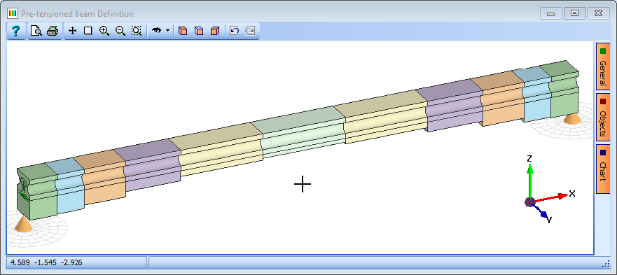
The last thing to do is use the Define field to open up the Section Definition form for sections 2 to 5 to change the PS beam component to the correct one in the library. A prompt will appear to change other sections but answer “No” to this each time it appears. The results beam should look like:
Save the project file as “My EU Example 8_3.sst” before closing the program.
Summary
This example explains how to create user libraries of sections from data that has been pre-prepared in, and imported from, AutoCAD in DXF format. This may be useful when considering sections that are not available in the default “Concrete Beam” and “Steel Section” libraries provided in Autodesk Structural Bridge Design. SXF files are also created to store data pertaining to reinforcement and tendons.
In addition, the example shows how to extract design sections from design beams at any location along the beam.
Note that after a section has been defined with data imported from a DXF file it may be necessary to re-assign the material properties for the reinforcement and tendons before analysing the section.