
8.6 Creating Design Section Load Case From Analysis Results
Subjects Covered
- Transfer of results from structural analysis model to design section load tables
Outline
Reinforced Concrete column, 5m high, fully fixed at its base and loaded with 160kN in the positive global X and Y direction together with a -1000kN vertical load downwards at the section centroid at the top of the column.
Reinforcement is 20mm bars with 40mm cover.
The concrete is grade 40 and the reinforcement grade 500.
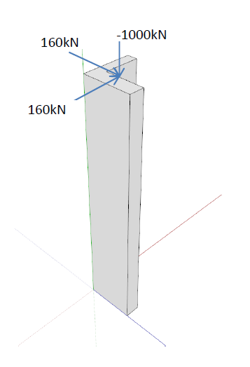
Carry out a structural analysis to determine the load effects at the base of the column and carry out a section analysis at ULS to determine the angle of the NA when these loads are applied and what additional axial load can be applied.
Carry out a shear analysis in two orthogonal directions to determine what shear reinforcement is necessary to resist the applied loads.
Procedure
Create Design Section
Start the program and click the Home New button.
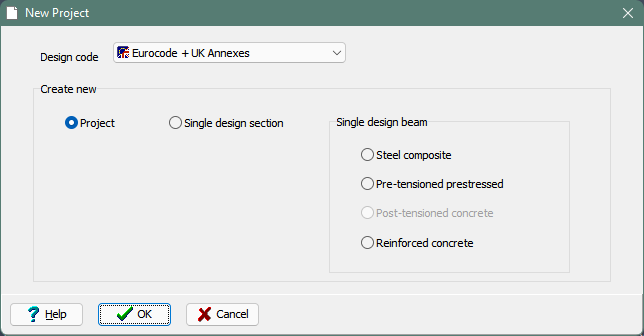
On the New Project form, ensure “Project” is selected, set the design code to “Eurocodes + UK Annexes” and click ✓ OK to create a new project.
Set the Project Title to “Design Section Transfer”, a subtitle of 'Simple column analysis', a job number of “8.6” and put your initials in the Calculations by field.
Define two materials, one for grade 40 concrete (parabolic rectangular) and the other for grade 500 reinforcement steel (horizontal).
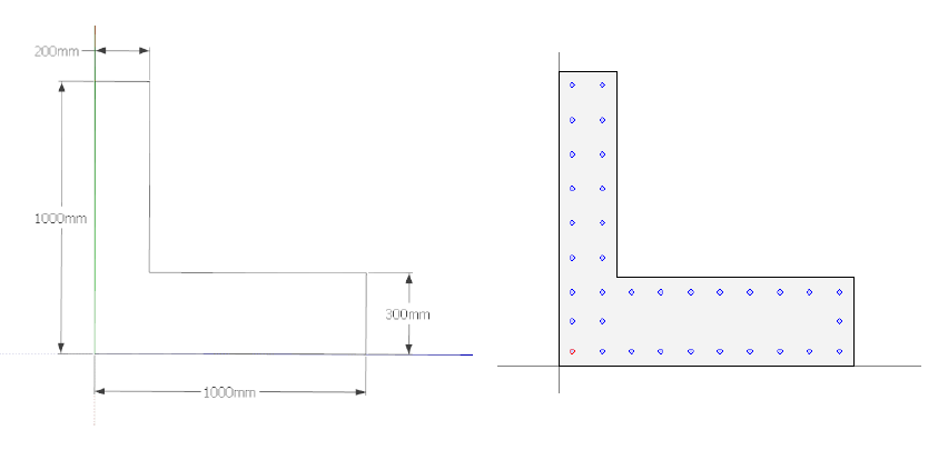
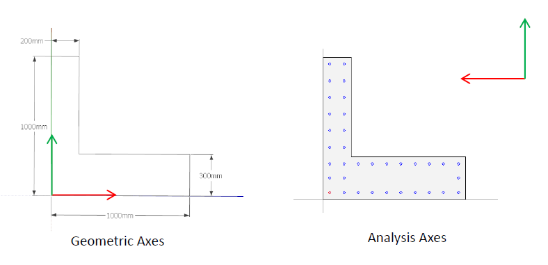
Create a design section using an 'L' parametric shape using the dimensions shown above and assign the concrete material. The corner of the L should be at the origin.
Define reinforcement with the number of 20mm diameter bars as shown by placing bars in the corners using 'one bar by two covers' and then using these as snap points to draw additional bars between them.
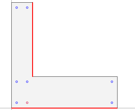
Don't forget that you can place one bar by two covers on two faces that are not connected, as shown below, to ensure that bars are lined up.
Create Structure
Create a refined structural model using a 3D sub-model and drawing a single sub-model member from (0,0,0 to 0,0,5). This can then be split into 10 equal sized elements forming the column. Fully fix the base node at the origin.
In Structure properties navigation window assign the pre-defined section by clicking on the Create Section and Beam Groups task, and then assigning the structure property to all the 10 members using the 'centroid' as a reference and setting 'Gross' section properties.
Use the File | 3D Elements View main menu item to display a 3D view.
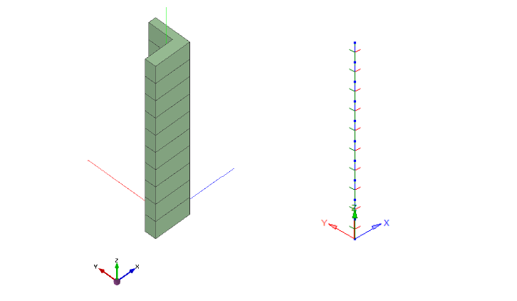
The orientation of the section is not as expected and is controlled by the local axes as shown (red is local y and green is local z) which suggests that although the section geometry was defined using one coordinate system with the x axis out of the section the assignment of the section to the structural element was done using a second system, with its origin at the centroid, with the x axis into the section and the y axis orientated from right to left.
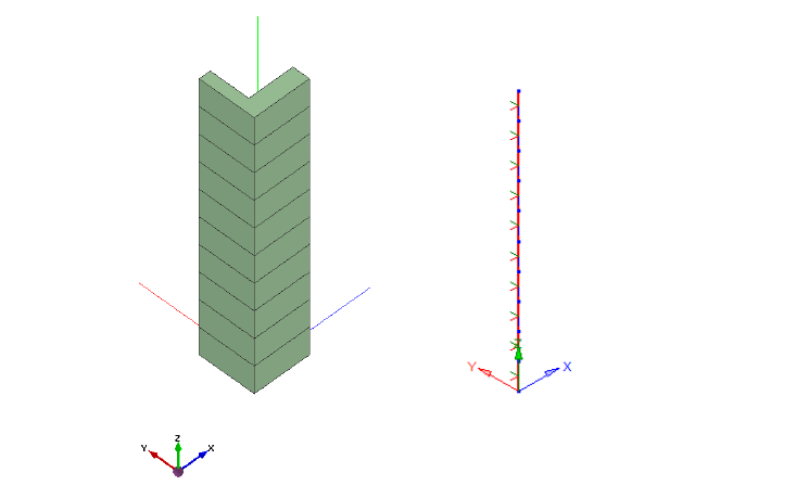
To orientate the section in the correct way the x axis can be reversed by “reversing the order” in the Member Details data form. This provides a 3D element view and local axis orientation as shown.
Nodal loads are then placed in the x y and z direction in one load case at the top of the column
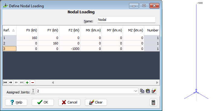
The analysis for the load case is carried out and the results displayed

The tabular results for the analysis for the base of the beam yield the following results:

Let's transfer the analysis result to a new design section loadcase:
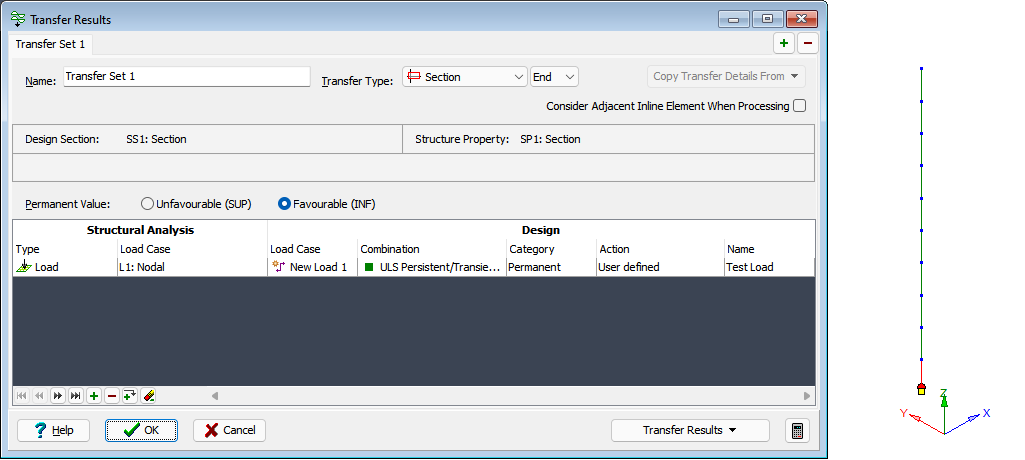
Go to Calculate | Transfer Results main menu item to display the transfer table form. Change the Transfer Type to “Section” and position to “End”. Click on the bottom beam element.
Click on the table + button and define a row as shown above, to map the structural analysis load L1 to a new design section load case as shown, with permanent value set to “Favorable”.
Select “Transfer Current Set to Design Section” from the Transfer Results drop down button, and click on ✓ OK to close the transfer form.
Open the new design section loadcase
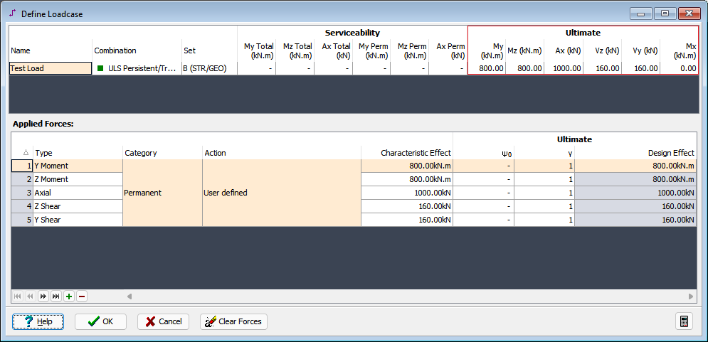
Notice the shear force sign difference in the design loadcase compared to the analysis results due to a difference in the sign convention.
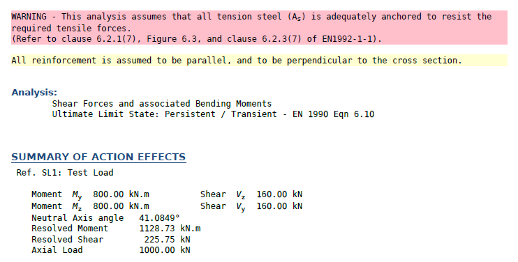
The analysis of the load case for ULS biaxial bending with axial force yields the following:
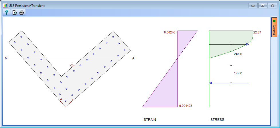
Which shows that the bending moments are both of the correct sign as the compression zones are as expected.
Looking at the results for the test load case where both shears are applied together we can see that the resolved shear is the correct magnitude.
Summary
In this example results were transferred from an analysis model to a design section load table.