
8.1 Line Beam Integration
Subjects Covered
- 3 span line beam
- Import precast beam
- Dead and SDL load optimisation
- Transfer results to beam module
- AASHTO Distribution factors
Outline
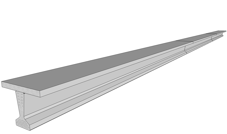
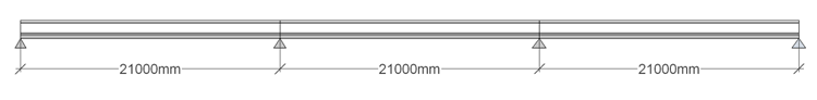
In this example we are going to create a 3 span line beam with three equal spans of 21m. The line beam is constructed from 3 precast beams which are placed on bearings and made continuous by pouring the slab and diaphragm.The concrete is poured in one stage.
We will create a line beam structure then use the prestress beam files created in Example 4.3 to define the section properties for the model. We will then carry out a load optimisation for dead, SDL, Gra1a, Gr1b and Gr5 live loadings. When this has been completed we will transfer the load effects into the beam loading tables making use of the direct link between the structure and beams.
Procedure
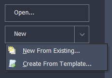
Start the program and select the New drop down button item Create From Template and pick the “EU Project” template.
From the main menu select File | Titles to give a project title of “3 Span Line Beam” with a sub title of “Example 8.1” and a Job Number: of “8.1” and put your initials in the Calculations by: field.
Click “OK” to close the form.
Create line beam geometry
- Click on Add Model | Line Beam in the toolbar at the top of the Structure Definition pane.
- The Line Beam Geometry form will open.
- Set the Number of Spans to “3.”
- Click in the Span Length column on each row of the table on the form and enter “21m” for the span lengths.
- Leave the support conditions at their default values and change the Divide Shortest Span into field to “21.” The Divide Longest Span into field will automatically update to “21”. Leave it set to this value.
- Click ✓ OK to close the form.
Create the Design Beams
Only two design beams are required, one end span beam and one centre span beam, as the structure and loading is symmetrical and it is expected that each end span will have the same design.
Change the navigation window to Design Beams.
Use the
 toolbar button to add an Existing Design Beam and select the file “EU Example 4_3.sam” that was created using the steps in section 4.3 of this Manual.
Select the beam in the navigation window and right click to Rename it “End Span.”
Right click again to select Copy which will create a copy of the first beam.
Rename this to “Centre Span.”
This process has provided two linked beams which are connected to the same file. As the load effects acting on these beams are going to be different, it is important to embed these beams into the project as separate entities with separate load effects tables.
Click the Embed All Linked Beams task at the bottom of the navigation window, which will break the link to the single file. It is not necessary but, if desired, the embedded beams can be re-linked back to separate beam file once the analysis has provided the load effects for the beams.
Define Structure Properties
Having defined the geometry of the structure and the design beams we now need to define the structure properties.
Change to the Structure Properties navigation window and click on the Create Section and Beam Groups task at the bottom of the window.
This will create two entries for an end and centre span. However we wish to assign cracked section properties for the slab over the internal supports which mean we need a different entry for the left and right end spans to ensure the section properties are calculated accurately
Select the End Span object in the navigation window, which will open up a data form, and change the Description to “Left Span” before closing with ✓ OK.
Then right mouse click in the navigation window to select Copy to create a third property. The Description for this in the data form should be changed to “Right Span” before closing with ✓ OK.
Select the Left Span object in the navigation window and in the resulting data form, change Type: to “Transformed Section” and the Cracked Section | from right | Proportion to “0.15”. In the graphics window click on the left span to select all the beam elements in that span. Close the form with the ✓ OK button.
Repeat this for the Right Span as a “Transformed Section” but this time the Cracked Section will be from the left as opposed to the right.
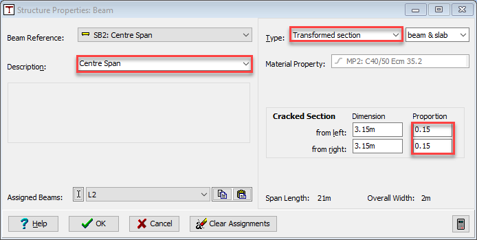
Repeat this for the Centre Span as a “Transformed Section” but this time enter the proportion of “0.15” at both ends.
Load Optimization
The next step is to carry out a load optimization on the line beam.
Click on the Data | Automated Loading main menu item to open the Automated Loadings form.
Check the tick boxes for “gr1a (Tandem System)”, “gr1b (Load Model 2)” and “SV80” (use + icons to make the tickbox available).
Set the Amplification factor... field to “no point in line beam."
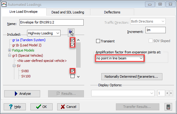
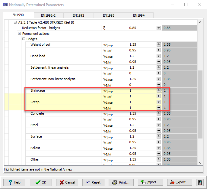
Click on the Nationally Determined Parameters... button to open the Nationally Determined Parameters sub-form.
In this sub-form select the EN 1990 tab and scroll down to the values for Clause A2.3.1 Table A2.4(B) and click on the + button for “Permanent Actions” to expand this sub-section. In this sub-section ensure that the values for and “shrinkage” and “creep” are both set to “1”. Click “OK” to close the Nationally Determined Parameters sub-form.
Click the Analyse button on the Automated Loadings form.
Click on the Results... button to see the Results Viewer and close it using the Exit button.
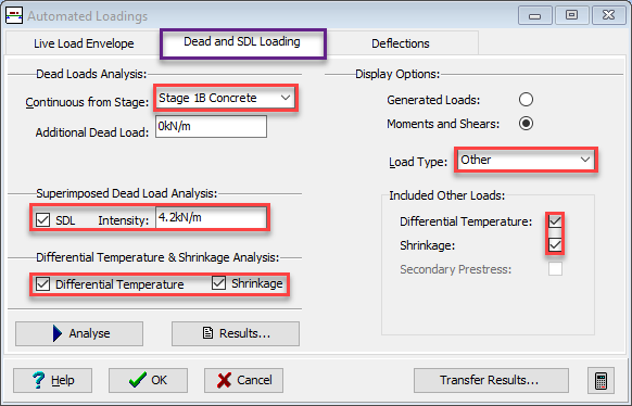
Select the Dead and SDL Loading tab on the Automated Loadings form.
Set the Continuous from Stage field to “Stage 1B Concrete” and change the value of SDL Intensity to “4.2kN/m”.
Make sure Analyse for SDL, Analyse for Diff. Temp. and Analyse for Shrinkage are all ticked.
Click on the “Analyse” button to carry out the load optimization.
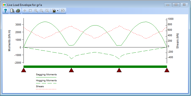
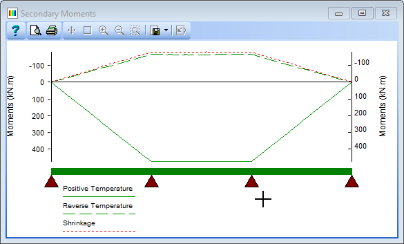
When it has completed, select “Other” in the Load Type: field and ensure the available tick boxes below this field are ticked. The graphics will show the results shown below.
Transfer Results
Once the loads have been generated, the next step is to transfer the enveloped analysis results into the appropriate beam load effect tables.
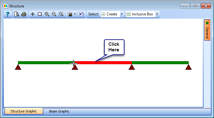
To do this, click on the Transfer Results button. This opens the Transfer Results form.
Click the left span on the graphics window to select the beam into which we want to transfer the results. The beam will be highlighted in red and the details shown in the Design Beam field.
This form is used to match the load cases in the line beam with the design load cases in the beam file. This could be completed one line at a time by clicking in the Design Load Case column to select the required design load case in the beam file then click in the Automated Load Results column and select the loading you want to transfer into that load case. Ensure that the ULS Factor in are all set correctly. Fortunately there is a quick way to fill this form in with all the default values being applied in one go.
At the bottom of the form is a set of toolbar icons, the last one of which is
 set default mapping which is exactly what we want to fill the form in as shown below. Adjustments can be made if necessary but the defaults are ideal for a line beam analysis such as this. Only the load cases that have been selected and analysed will be mapped.
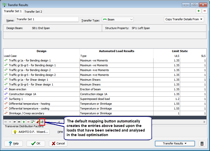
The centre span beam can be defined on the same form by adding a second transfer set with the + button in the top right corner of the form, selecting the middle beam on the graphics window and selecting the Set Default Mapping button again.

The next step is to calculate the transverse distribution factors. To do this, click on the AASHTO D.F. Wizard... button. This will open the Distribution Factors Wizard form.
Set the Table 4.6.2.2.1-1 Cross Section: field to “K” (if not already set) and leave all other values in the table at the default settings.
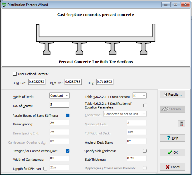
When you have entered this data, click ✓ OK to close the wizard form.
The Transfer Results form will now display the DFM values.
Click on the Transfer Results button and select “Transfer All Sets” to transfer the factored load effects into the appropriate design beam load tables for both beams.
Close the Transfer report form, the Transfer Results form and the Automated Loading form with ✓ OK before opening the Design Beam navigation window.
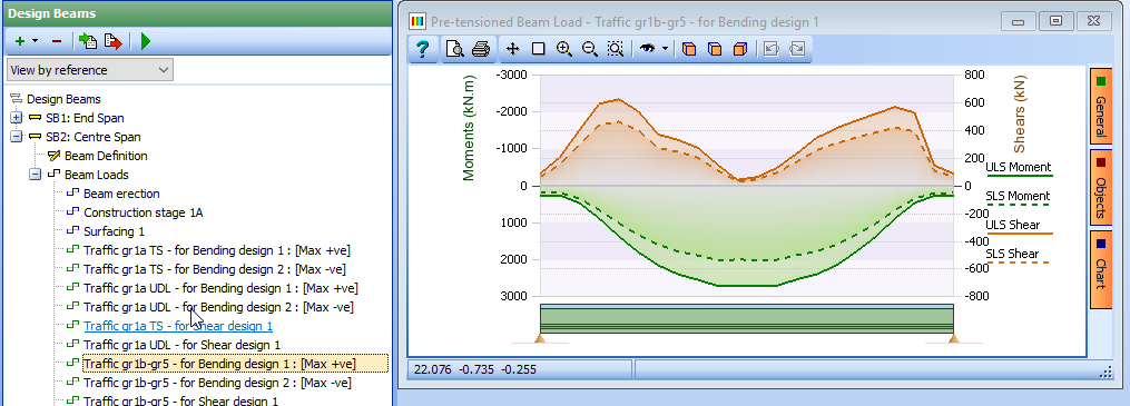
Select any of the load tables that have been transferred to see the results.
Click on the File | Save As main menu item and enter the filename “My EU Example 8_1.sst”.
Click on the “Save” button to save the file.
Close the program.
Summary
In this example we created a 3 span line beam and assigned structure properties to it, using a pre-stressed concrete beam file created in an earlier example. Although we only had one beam file we used it to create two embedded design beams, one for the end span and the other for the central span. These two design beams were used to create 3 separate structure properties, one for each span. We then used the load optimization to create Dead, SDL, Diff temp/shrinkage and Live loads. The load effects were then transferred to the design beams, using the AASHTO Distribution Factor Wizard to calculate distribution factors based on the geometry of the structure.
It should be noted that the Eurocode road traffic load effects for gr1a have been split, during the transfer, into two separate tables in the design beams; one for the Tandem system part and the other for the UDL part. This is necessary as it is possible that the psi factors may be different for each component which will affect how they are combined together for different combinations or whether the traffic loading is a leading load or an accompanying load.