
Right-Click Menus
To quickly access often-used commands relevant to the current task, right click in the Graphics window. For additional commands that control part appearance, right click directly on the model.
This topic is divided into two sections--Setup tasks and Results tasks. The menus for each are presented followed by descriptions. Links to other topics are provided where appropriate.
Right-Click Menus for Setup Tasks
On every Setup task, use the right-click menus to change the selection type, select and deselect items, and open the appropriate Quick edit dialog. Additionally, access commands specific to the current task.
Right click off model
Right click on part (Materials task)
Right click on part (Boundary Conditions task)
Right click on part (Mesh task)
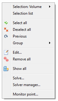
Right click off model
Selection type
- Select either Volume, Surface, or Edge.
- Note that the Selection Type can also be set from the Setup (tab) > Selection (panel).
Selection list
- Toggle the display of the Selection List.
- The Selection List displays items that have been selected in the Setup tasks. This is especially helpful for knowing exactly which items are selected.
Select All / Deselect All / Previous
- Acts on the active Selection Type.
- For more about selecting entities
Group
- Create a group of selected items
- Select a group containing items of the same type as the current Selection Type.
- For more about groups
Edit
- Opens the Quick edit dialog for the active task.
- Apply and modify setup conditions.
Remove all
- Deletes all settings of the type defined in the active task.
Show all
- Resumes visibility of all hidden parts.
Solve
- Manage and run multiple analyses
- For more about the Solver Manager
Monitor Point...
- Create and manage monitor points for assessing results at specific locations.
- For more about monitor points
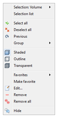
Right click on part (Materials task)
Selection type
- Select either Volume, Surface, or Edge.
- Note that the Selection Type can also be set from the Setup (tab) > Selection (panel).
Selection list
- Toggle the display of the Selection List.
- The Selection List displays items that have been selected in the Setup tasks. This is especially helpful for knowing exactly which items are selected.
Select All / Deselect All /Previous
- Acts on the active Selection Type.
- For more about selecting entities
Group
- Create a group of selected items
- Select a group containing items of the same type as the current Selection Type.
- For more about groups
Shaded, Outline, Transparent
- Change the appearance of selected parts.
Favorites / Make favorite
- Select or designate commonly used materials
- For more about Favorites
Edit
- Opens the Quick edit dialog for the active task.
- Apply and modify materials.
Remove
- Unassigns the material applied to the selected object.
Remove all
- Unassigns all materials.
Hide
- Temporarily removes the selected part from view.
- Hiding allows easy access to objects in the background.
- Alternatively, use the mouse to hide an object as described here.
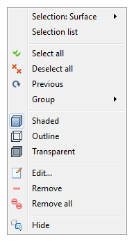
Right click on part (Boundary Conditions task)
Selection type
- Select either Volume, Surface, or Edge.
- Note that the Selection Type can also be set from the Setup (tab) > Selection (panel).
Selection list
- Toggle the display of the Selection List.
- The Selection List displays items that have been selected in the Setup tasks. This is especially helpful for knowing exactly which items are selected.
Select All / Deselect All /Previous
- Acts on the active Selection Type
- For more about selecting entities
Group
- Create a group of selected items
- Select a group containing items of the same type as the current Selection Type
- For more about groups
Shaded, Outline, Transparent
- Change the appearance of selected parts.
Edit
- Opens the Quick edit dialog for the active task.
- Apply and modify boundary conditions.
Remove
- Unassigns the last boundary condition applied to the selected object.
Remove all
- Unassigns all boundary conditions.
Hide
- Temporarily removes the selected part from view.
- Hiding allows easy access to objects in the background.
- Alternatively, use the mouse to hide an object as described here.
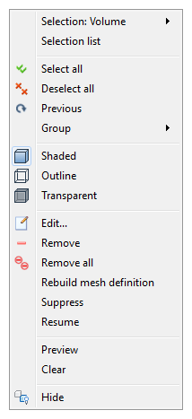
Right click on part (Mesh task)
Selection type
- Select either Volume, Surface, or Edge.
- Note that the Selection Type can also be set from the Setup (tab) > Selection (panel).
Selection list
- Toggle the display of the Selection List.
- The Selection List displays items that have been selected in the Setup tasks. This is especially helpful for knowing exactly which items are selected.
Select All / Deselect All / Previous
- Acts on the active Selection Type
- For more about selecting entities
Group
- Create a group of selected items
- Select a group containing items of the same type as the current Selection Type
- For more about groups
Shaded, Outline, Transparent
- Change the appearance of selected parts.
Edit
- Opens the Quick edit dialog for the active task.
- Apply and modify mesh settings.
Remove
- Unassigns the manual mesh setting applied to the selected object.
Remove all
- Removes all mesh definitions.
Rebuild mesh definition
- Update the mesh distribution after modifying the mesh definition history.
- For more about Mesh History
Suppress / Resume
- Remove (or restore) parts from the analysis.
- For more about Suppression
Preview / Clear
- View the mesh prior to generating the complete, three-dimensional mesh
- For more about Mesh Preview
Hide
- Temporarily removes the selected part from view.
- Hiding allows easy access to objects in the background.
- Alternatively, use the mouse to hide an object as described here
Results tasks
On every Results task, use the right-click menus to modify the appearance of the model, part, or results object.
Right click off Model
Right click on Part
Right click on Plane or Iso Surface (while either Planes or Iso Surfaces task is active)
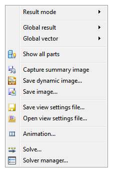
Results: Right click off model
Result Mode
- Select the results mode.
- This is the same as selecting the mode from the Results Task panel.
Global result
- Select the result displayed on the model.
Global vector
- Enable vectors on model surfaces.
- Select the displayed vector quantity.
Show all
- Resumes visibility of all hidden parts.
Capture summary image
- Save an image and apply the same view to all scenarios in the design study. Compare results in the Design Review Center.
- For more about the Design Review Center.
Save dynamic image...
- Save an image that can be navigated in the Autodesk® CFD Viewer.
Save image...
- Save a static (bmp, gif, tif, jpg).
Save view settings... / Open view settings
- Save the current view for use later or with other models.
- For more about the view settings file.
Animation...
- Animate saved iterations or time-steps.
- For more about animation.
Solve...
- Specify the physics and run the analysis
- For more about Solving.
Solver Manager...
- Manage and run multiple analyses
- For more about the Solver Manager.
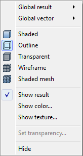
Results: Right click on part
Global result
- Select the result displayed on the model.
Global vector
- Enable vectors on model surfaces.
- Select the displayed vector quantity.
Shaded, Outline, Transparent, Wireframe, Shaded mesh
- Control the appearance of the selected part.
- These controls are also on the Quick Access toolbar and on View (tab) > Appearance (panel) > Visual Style
Show result
- Display results contours on surfaces of the selected part
Show color
- Display a selected color on the model instead of the global result quantity
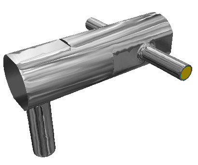
Show texture
Map an external texture map to the model.
Textures are surface images that can be assigned to parts. They change the appearance of a part to look like a real-world object or substance. They give your model a real world appearance by making visually provocative results images.
To impose a texture, right click on a part, and select Show Texture. A menu dialog appears with several dozen texture maps.
In the following example, a chrome texture map is assigned to the part:
Set Transparency
- Active only if transparency is enabled for the model or part
- Increase transparency by moving the slider toward 100%.
Hide
- Temporarily removes the selected part from view.
- Hiding allows easy access to objects in the background.
- Alternatively, use the mouse to hide an object as described here.
- To hide surfaces, click View(tab) > Appearance (panel) > Surface Blanking.
- An unobstructed view of an object must exist to hide it.
By default, suppressed parts are not visible when viewing results. To display them, open the Design Study bar, and expand the Materials branch of the Results branch. Check the box adjacent to each part to be displayed.
For more about displaying suppressed parts...
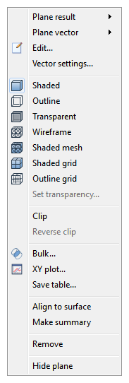
Results: Right click on Plane or Iso Surface
Use these right click menus to control the appearance of planes and iso surfaces.