
Chapter 9: Assigning Boundary Conditions
Previous: Exercise 2 | Next: Exercise 3
In the previous chapter, we discussed assigning, creating, and managing materials within the design study. In this chapter, we focus on how the design interacts with its surroundings. By assigning boundary conditions such as flow rate, pressure, and temperature to openings and other specific locations, we effectively "connect" the design with the physical world. Additionally, boundary conditions allow us to specify internal heat loading, such as heat dissipation often found in electronics thermal management simulations.
Boundary conditions define the inputs of the simulation model. Some conditions, like velocity and volumetric flow rate, define how a fluid enters or leaves the model. Other conditions, like film coefficient and heat flux, define the interchange of energy between the model and its surroundings.
Boundary conditions connect the simulation model with its surroundings. Without them, the simulation is not defined, and in most cases cannot proceed. Most boundary conditions can be defined as either steady-state or transient. Steady-state boundary conditions persist throughout the simulation. Transient boundary conditions vary with time, and are often used to simulate an event or a cyclical phenomena.
Using Boundary Conditions
To assign a Boundary Condition
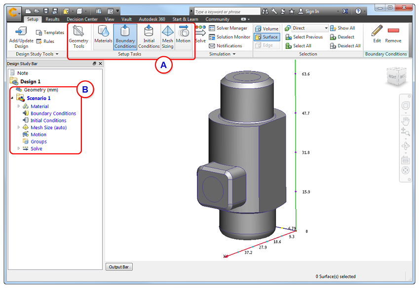
To begin, enable the Boundary Condition task from either the Setup (tab) > Setup Tasks (panel) (A) or from the Design Study bar (B):
To work close to the model
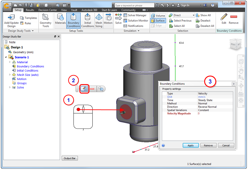
- Left click on the model entity (surface or part).
- Click the Edit button on the context toolbar.
- Specify settings in the Boundary Conditions quick edit dialog.
Alternatively, right click on the model entity or branch on the Design Study bar, and click Edit...
To work away from the model
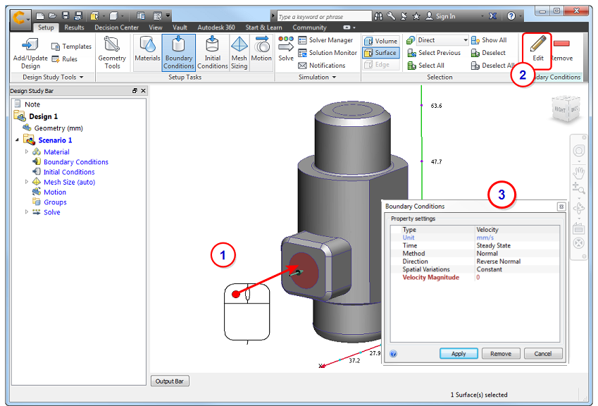
- Left click on the model entity (surface or part) to select it.
- Click Edit in the Boundary Conditions context panel.
- Specify settings in the Boundary Conditions quick edit dialog.
To assign the boundary condition in the quick edit dialog
- Set the Type of condition.
- Set the Units (if applicable).
- Set the Time Variation (Steady State or Transient).
- Apply condition-specific settings such as Normal or Component for Velocity or Static or Gage for Pressure. Change the flow direction for velocity, volume flow rate, or mass flow rate.
- Specify the value.
- Click Apply.
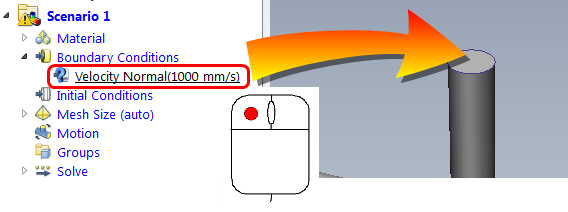
To define and then apply a boundary condition
An alternative workflow is to create a boundary condition before applying it to the model.
- Click Edit on the Boundary Conditions context panel. Alternatively, right click on the Boundary Conditions branch of the Design Study bar, and click New BC....
- Define the boundary condition in the Boundary Conditions quick edit dialog, and click Apply.
- Drag the unassigned setting from the Design Study bar onto the model entity:
To Remove a Boundary Condition
To remove a boundary condition from a specific entity (several ways):
- Left-click on an entity, and click the Remove icon from the context toolbar. (This removes conditions in the order they were applied.)
- Expand the Boundary Condition branch in the Design Study Bar, right click on a specified condition, and click Remove.
- Select the entity, and click Edit from the Boundary Conditions context panel. On the quick edit dialog, set the Type to that of the condition to be deleted, and click Remove.
To remove a single boundary condition from multiple entities:
- Expand the Boundary Condition branch in the Design Study Bar.
- Right click on the condition to remove.
- Click Remove.
To delete all boundary conditions:
- Right click on the Boundary Condition branch of the Design Study bar.
- Click Remove All.
Flow Boundary Conditions
Flow boundary conditions answer these questions:
- Is there flow?
- What drives the flow?
- Where does it enter and leave the model?
- What is its value?
Flow can be driven in several ways:
- specified flow rate
- velocity
- pressure
- internal fan or pump
- buoyancy due to natural convection
Flow boundary conditions are applied to exterior surfaces, and typically include:
Inlet | Outlet |
Flow rate | Pstatic = 0 |
P static = 0 | Flow rate |
Pstatic > 0 | Pstatic = 0 |
External fan (push) | Pstatic = 0 |
Pstatic = 0 | External fan (pull) |
Pstatic = 0 (internal fan) | Pstatic = 0 |
The most commonly used flow boundary conditions...
There are more flow boundary conditions available in Autodesk® CFD. The conditions listed above are the most commonly used. Click here to view descriptions of all flow boundary conditions in Autodesk® CFD...
Heat Transfer Boundary Conditions
Heat can come from a known temperature, a heat load (such as an electronic chip), radiation, or resistance to electrical current. Heat boundary conditions answer these questions:
- Is there heat in the design?
- Where?
- What value?
- Where does the heat leave the design?
- What is the reference ambient temperature?
The most commonly used heat transfer boundary conditions...
There are more heat transfer boundary conditions available in Autodesk® CFD. The conditions listed above are the most commonly used. Click here to view descriptions of all heat transfer boundary conditions in Autodesk® CFD...