
Chapter 7: Geometry Branch and Tools
Previous: Exercise | Next: Chapter 8
Use the Geometry branch to perform these three primary functions:
Set the analysis length units.
Specify the coordinate system for 2D models.
Access the Geometry tools.
Geometry settings made to a design apply to all scenarios within a design.
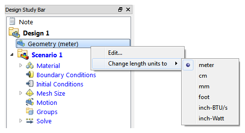
To set the units for the Design, select Length Units
- The default units are meters unless the default was changed in the User Preferences dialog or when launching from CAD.
- For geometries originating in most CAD systems, changing the units system changes the model dimensions to the new units. For example, if the object was 1 meter long, and units are changed to mm, it will be 1000 mm long. (Same physical size, different length value).
- For Pro/Engineer models, changing the units system only changes the analysis length unit; it does not change any dimensions in the model.
- The length units of each new design added to a design study are automatically set to the same as the other designs in the study.
- Changing the length units of an individual design causes the length units of every design to be changed.
- Length units cannot be changed if any design in the study has a scenario that has been run.
To set the coordinate system for 2D models
- Select Coordinate System from the right-click menu
- Select Cartesian, Axisymmetric about the X or Axisymmetric about the Y
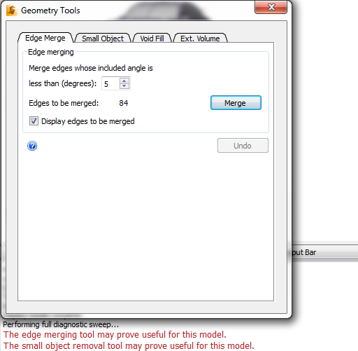
Geometry Tools
Geometry Tools allow for the modification and creation of geometry in the Autodesk® CFD interface. Tools like Edge Merging and Small Object Removal enable you to reduce the complexity of certain geometric features and therefore increase the speed of your analysis. Void Fill Creation and External Volume Creation provide the ability to create flow geometry inside the design study, separate from the original CAD geometry.
To access the Geometry Tools, click Setup > Setup Tasks > Geometry Tools. Alternatively, right click on the Geometry branch of the Design Study bar, and click Edit...
To join edges that meet at a common vertex below a specified inflection angle, use Edge Merging
Edge Merging unifies edges that meet at a common vertex at an inflection angle less than a specified tolerance. This tool provides the benefit of reducing the number of edges, especially small ones, which leads to reduced overall mesh density, and faster analysis times.
The inflection point is determined by the included tangency angle which has an upper limit in the Edge Merging dialog of 15 degrees.
About Edge Merging
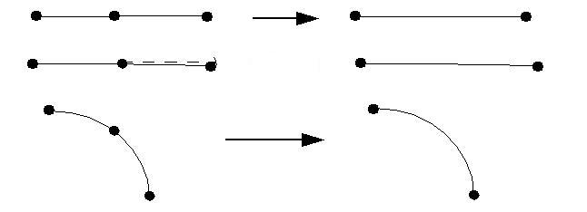
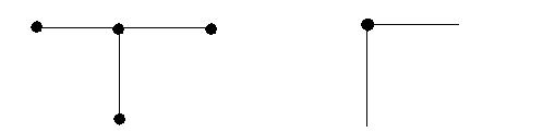
Edge Merging will have no effect if more than two edges meet at a vertex (as shown on the left). Likewise, it will not merge edges that meet at an included angle larger than the specified angle (shown on the right):
Optionally, click here for more about Edge Merging...
To remove small surfaces and edges that are too small to be seen, use Small Object Removal
Small Object Removal is a geometry repair tool, not a part suppression tool. It is better to suppress parts from the model in the CAD tool. This tool is designed to remove very small surfaces and edges that are typically too small to be seen.
Sliver surfaces often either prevent successful mesh generation or result in an excessive mesh density.
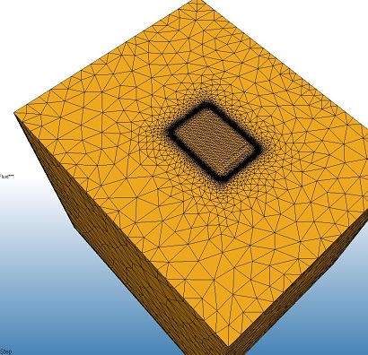 | 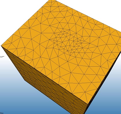 |
The box on the left has a very tiny sliver loop in the middle of the top surface. With this loop, the mesh density was very high in this region. The box on the right shows the effect after it was removed by Small Object Removal. The mesh density was considerably less.
Optionally, click here for more about Small Object Removal...
To create an internal flow volume within the physical solids, use Void Fill
The typical CAD model consists of the solid parts, but not fluid parts. The fluid region is usually contained within and around the solids, but in most cases is not explicitly constructed as part of the geometric model.
Geometry that consists only of solid parts will typically have openings where the working fluid (air, water, etc.) will enter and leave:
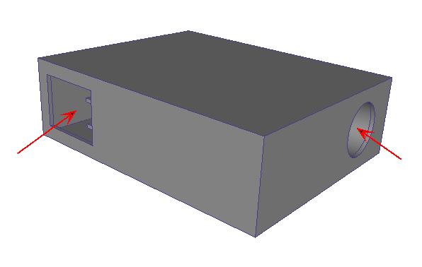
In this state, such a model is not suitable for a flow analysis (because of the lack of a flow part).
The Void Fill tool provides a facility to create capping surfaces that bound a water-tight internal void. The surfaces and volume that are created are actual geometry that can have boundary conditions, materials, etc., and are meshed as part of the simulation model.
Optionally, click here for more about Void Fill...
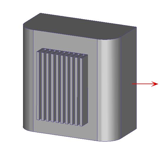
To create a part for the surrounding flow, use External Volume Creation
Many devices are immersed in a fluid (air or water, for example). A key factor in the design of such parts is how the fluid flows around the device. Examples include:
- Motorcycles and bicycles
- Aircraft
- Automobiles
- Electronic devices subject to external natural convection
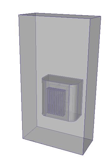
In all of these cases, the volume that surrounds the device is rarely included as part of the production CAD model. To analyze the flow, it is necessary to add a surrounding volume to the model.
With the External Volume tool, the surrounding air (or fluid) can be constructed directly on the simulation model within Autodesk® CFD, without having to add it to the CAD geometry.
Optionally, click here for more about External Volume Creation...
A Note about Exercise 1
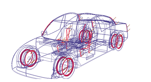
In Exercise 1, we closed the Geometry Tools dialog, even though messages advised that several edges could be merged and that using Geometry Tools would be helpful.
Why?
After examining the model, it was clear that most of those edges are on external surfaces of the car. Because the intent is to study the flow inside the cabin, Geometry tools would not improve the analysis performance.
When to Use Geometry Tools:
The tabs are arranged in the recommended order of use:
Edge Merging --> Small Object Removal --> Void Fill --> External Volume.
Note that using the tools in a different order may lead to unexpected results and possibly errors.
Apply Geometry tools before assigning any other model settings (boundary conditions, mesh sizes, etc.). This is because Geometry tools add and remove geometric entities from the model which may cause existing settings to be removed.
Keep in mind that the Geometry Tools are optional. You may choose to use the tools in your CAD system to merge edges, eliminate small objects, and create internal or external flow volumes. There are advantages and disadvantages to both.
Using Geometry Tools in Autodesk® CFD provides an easy way to modify your model and create flow volumes without adding or removing geometry from the CAD model. However, making changes in the CAD model provides greater control of the features that are added or removed.