
Exercise 3
Previous: Chapter 9 | Next: Chapter 10
This exercise teaches how to assign boundary conditions in Autodesk® CFD.
Click Boundary Conditions on the Setup tab:
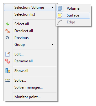
Right click off the model. Click Selection type, and Volume.

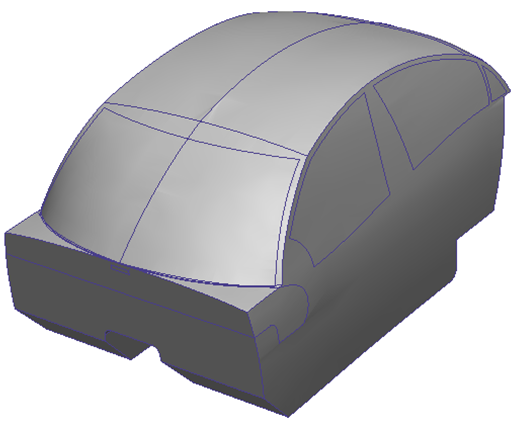
Hide the following parts:
Body of the car
Wheels
The six windows
Windshield
Rear window
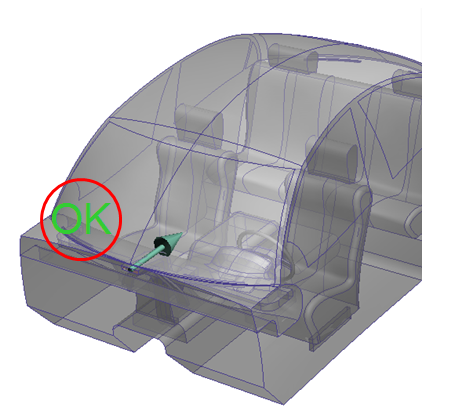
The model should look like this:
Right click off the model. Click Selection type, and Surface.
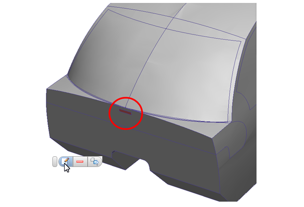
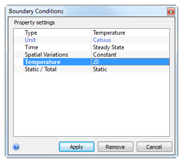
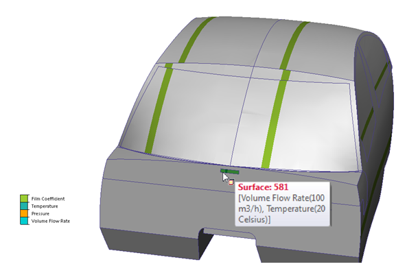
Cold air enters the cabin through the rectangular opening below the windshield. We will assign a temperature and a flow rate to this surface. Select this surface and click the Edit button in the context toolbar.
Type = Temperature, Unit = Celsius, Temperature = 20. Click Apply.
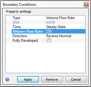
To apply the flow rate to the same surface, right click and select Previous from the menu.
Right click, and select Edit...
Type = Volume Flow Rate, Unit = m3/h, Volume Flow Rate = 100.
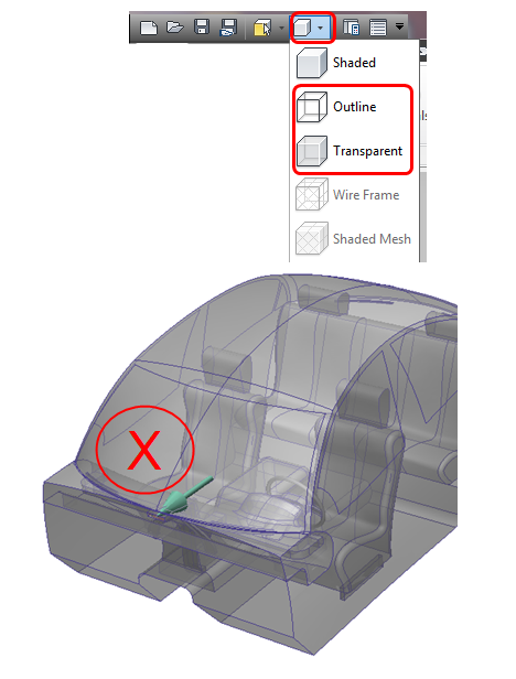
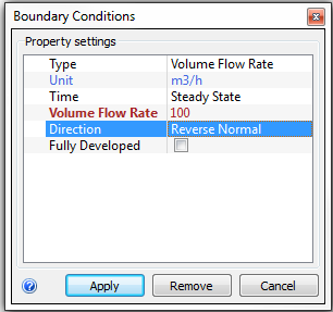
To ensure the flow direction is correct, display the model as Outline or Transparent from the Quick Access toolbar. Observe the flow direction arrow. If it is incorrect, click Reverse Normal in the Direction line of the Boundary Conditions dialog. Click Apply.
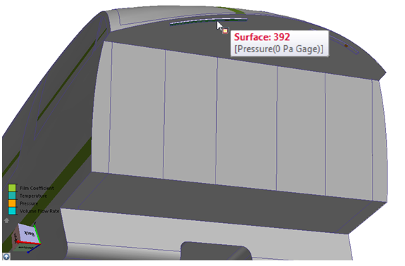
Change the model appearance back to Shaded, and rotate the model. Select the two arc surfaces at the rear of the cabin. Click the Edit button in the context toolbar.
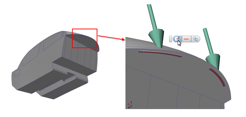 Note: Flow leaves the cabin from here.
Type = Pressure, Pressure = 0. Click Apply.
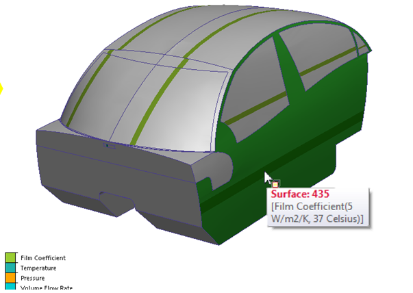
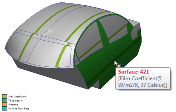
To simulate a stationary vehicle in hot conditions, apply a film coefficient to the sides and top of the passenger cabin. Select the following surfaces, and click the Edit button on the context toolbar:
The four surfaces on the right side
The four surfaces on the left side
The 10 surfaces on the top.
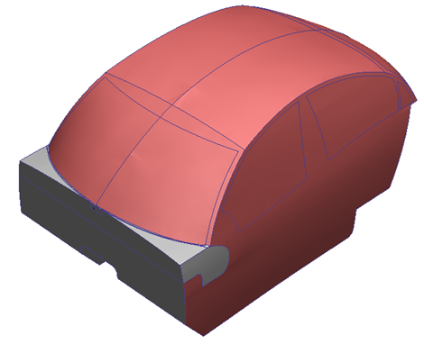
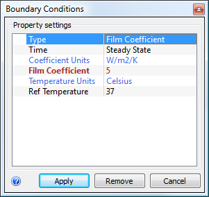
Type = Film Coefficient, Coefficient Units = W/m2/K, Film Coefficient = 5, Temperature Units = Celsius, Ref Temperature = 37. Click Apply.
 Note: This analysis assumes a worst-case approximation of heat transfer to the outside environment. A more detailed and precise study of heat loss to the environment is possible in Autodesk® CFD. It would require modeling the airspace around the vehicle. Many times this is not necessary, as a conservative estimate of heat loss – the approach used here - will provide a worst-case scenario in a much shorter time. This provides more time for comparisons of alternate designs.
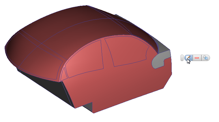
Confirm all correct boundary conditions are applied:
Compare stripe colors on model surfaces to the legend in the lower left corner.
Additionally, hover the mouse over surfaces to see the applied boundary conditions, units and values.
If any condition is incorrectly assigned, please correct it now.
End of Exercise.