
Using the Clipping Plane
Interaction > Clipping
Use the Clipping module to clip objects, hide parts of the scene on one side of a plane, for construction evaluation purposes and look at solid bodies. This is useful for construction evaluation purposes.
Learn about clipping planes in VRED with this Clipping Plane video.
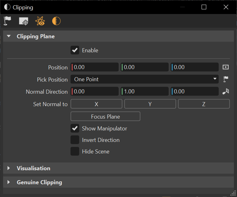
How to Enable the Clipping Plane
- Select Interaction > Clipping to open the Clipping module.
- Select Enable Clipping.
How to Position the Clipping Plane
In the Clipping module, click
 Pick Position, then Shift-click the point in the scene where you want the clipping plane.
Adjust the position of the plane by doing any of the following:
- To reposition the clipping plane, use the Position controls. Either enter numbers directly into the fields or click-drag within the fields.
- To enable the picking of points in the render view to reposition the clipping plane, use the dropdown for choosing the number of points required for repositioning the clipping plane. Click Pick Position icon and use Shift-click for selecting points and follow the prompt(s) in the bottom left corner of your screen.
- To position the center of the clipping plane at 0,0,0, next to the Position fields, click
 .
. - To set the direction of the clipping plane surface normals, either enter numbers directly into the Normal Direction fields or click-drag within them.
- To set the normals facing the camera axis, click
 .
. - To flip the clipping plane and its normals to face a selected axis, use Set Normal to.
- To change the view displayed to that of the focus plane, use Focus Plane.
- To display the clipping plane manipulator, enable Show Manipulator. Hold down Shift and drag the manipulator handles to adjust the position, using a mouse.
- To invert the direction of the plane, making the opposite side of the scene visible, enable Invert Direction.
- To hide the scene in the render view to only display the clipping plane, use Hide Scene.
How to Change Clipping Plane Appearance
From the Clipping module, use the controls under Visualization to change how the clipping plane looks.
- Show Clipping Plane - Enable to show the plane or disable to hide it.
- Plane Color - Set the color of the clipping plane. You can keep the grid visible, while hiding the plane.
- Show Grid - Enable to show the grid or disable to hide it.
- Grid Color - Set the color of the grid. You can keep the clipping plane visible, while hiding the grid.
- Show Contour - Enable to show the line around the part of the object clipped by the plane or disable to hide it.
- Clone Contour - Click Clone, then Shift-click the contour line to clone it. Once the clipping plane is translated, the clone will be visible.
- Contour Width - Set the thickness of the contour line.
How to Hide Everything in the Scene Except the Clipping Plane
In the Clipping Plane section, enable Hide Scene.
How to Align the Camera Parallel to the Clipping Plane
In the Clipping module, under Visualization, enable Show Clipping Plane. This is the inverse of Align, which positions the plane relative to the camera.
How to Create Geometry from the Clipping Contour
In the Clipping module, under Visualization, click Clone Contour. This creates a geometry node from the clipping contour. This node, named Clipping Contour, appears in the Scenegraph.
How to Set a Clipping Plane Path (Genuine Clipping)
You can set the clipping plane to move along a predefined path. A path can either be a line geometry contained in the original model or a continuous part of the clipping plane itself.
- In the Clipping module, under Genuine Clipping, click Pick Clipping Path.
- Shift-click and select a line geometry in the scene, including any displayed clipping contour.
- Adjust speed with the Speed controls.
- Move the clipping plane along the path, using the mouse wheel, while holding down Shift.
When you reposition the clipping plane, the path is discarded.