
Constrain components
Learn how to use Constrain Components to position two or more components relative to each other, reduce degrees of freedom in the assembly, and create a Constraint Relationship in Fusion.
Design > Assemble > Constrain Components ![]()
Create an align constraint
Constrain two components so their selected geometry is coplanar, coincident, or concentric with each other. The alignment type is automatically determined by the combination of selected geometry.
On the toolbar, click Assemble > Constrain Components
 .
.The Constrain Components dialog displays.
In the dialog, select Align
 constraint Type:
In the canvas, identify the primary component that you want to constrain, then select a face, edge, or vertex to position.
In the dialog, activate the Geometry selector for Component 2.
In the canvas, on a second component, select a face, edge, or vertex to position relative to the first component's selected geometry.
In the canvas, Component 1 moves to Component 2. In the dialog, a new constraint row is added to the table.
(Optional) In the table, locate the active Constraint row, then adjust its settings:
Distance Offset: Enter the distance value to offset the selected geometry from each other.
Flip
 : Flips the orientation of the selected geometry.Tip: To add more constraints to create a Constraint Set, click Add Constraint
 to add another constraint row. At any time, select a row in the table to activate it and edit its settings.
Click OK.
The Align Constraint is created between the components. If you created one row, a new assembly Constraint displays in the Browser > Relationships folder. If you created more than one row, a Constraint Set is added with multiple constraints nested under it.
Create an angle constraint
Constrain two components so their selected geometry is positioned with a relative angle between them.
In the dialog, select Angle
 constraint Type.
In the canvas, identify the primary component that you want to constrain, then select a face, edge, or vertex to position.
In the dialog, activate the Geometry selector for Component 2.
In the canvas, on a second component, select a face, edge, or vertex to position relative to the first component's selected geometry.
In the canvas, Component 1 moves to Component 2. In the dialog, a new constraint row is added to the table.
(Optional) In the table, locate the active Constraint row, then adjust its settings:
- Angle Offset (Angle constraint): Enter the angle value for the relative angle between the selected geometry.
- Flip : Flips the orientation of the selected geometry.
Click OK.
A Angle Constraint is created between the components so there is a constrained relative angle between the selected geometry.
Create a center constraint
Constrain two components one component is centered between two faces of another component.
In the dialog, select Center constraint Type.
Select a Position Mode for Component 1, then select it's corresponding geometry in the Canvas:
- Simple: Centers one face on the second component between two faces of the first component.
- Face: Select a face on the first component to constrain.
- Between Two Faces: Creates a constraint that is centered between two faces of the second component component.
- Face 1: Select the first face to center the constraint between.
- Face 2: Select a second face to center the constraint between.
- Simple: Centers one face on the second component between two faces of the first component.
Select a Position Mode for Component 2, then select it's corresponding geometry in the Canvas.
Note: Between Two Faces must be selected for at least one component. If Simple position mode is selected for Component 1, Between Two Faces is automatically selected for Component 2.(Optional) In the table, locate the active Constraint row and click Flip
to flip the orientation of the selected geometry.Click OK.
A Center Constraint is created between the components so one component is centered between two faces of the other.
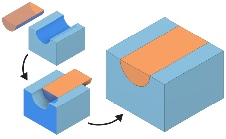
Create a tangent constraint
Constrain two components so one selection on the first component maintains tangency with geometry on a second component.
- In the dialog, select Tangent for the constraint Type.
- In the canvas, identify the primary component that you want to constrain, then select a face, edge, or vertex to position.
- In the dialog, activate the Geometry selector for Component 2.
- In the canvas, on a second component, select a face, edge, or vertex on the second component to maintain tangency to.
- (Optional) If you selected face geometry to constrain:
- Select All Faces so Component 1's selected face transition across all faces of the Component 2’s selected body.
- Unselect All Faces to maintain tangency to only Component 2's selected face.
- (Optional) In the table, locate the active Constraint row and click Flip to flip the orientation of the selected geometry.
- Click OK.
A Tangent Constraint is created between the components so one component maintains tangency with geometry on a second component.
Tips
- Apply Ground To Parent to one component to fix it in place at its initial position, then create constraints to position components relative to the grounded component to build up the assembly.
- To add more constraints to create a Constraint Set, click Add Constraint to add another constraint row. At any time, select a row in the table to activate it and edit its settings.