
Event Simulation 01
Plastic Deformation of Thick Hollow Sphere with Internal Pressure.
Case Description
This accuracy verification example demonstrates the reliability of the event simulation solver in quantifying the following three phenomena:
- Time-dependent applied loads
- Nonlinear material behavior, specifically plastic deformation when loaded beyond yield
- Using symmetry to determine the behavior of a full body using only a partial, much smaller, representation
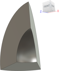
The model is a one-sixteenth symmetry representation of a thick-walled hollow sphere. A uniform pressure is applied to the interior cavity surface. The pressure magnitude is ramped up linearly. At some point in the event, plastic deformation begins to occur at the interior surface. As the event simulation continues, more of the wall thickness reaches plastic stress levels progressively. Eventually, the outer surface reaches the yield stress, at which point the sphere begins to expand rapidly. The derivation of the pressures required to just reach the plastic state at the interior and exterior surfaces is shown on this page. The Fusion results are compared to the theoretical results.
A perfectly plastic material is assumed, meaning that the slope of the stress-strain curve is flat (zero) once yield occurs. In other words, there is no work hardening of the material. This assumption makes the theoretical derivation simpler.
Frictionless constraints represent the symmetry conditions at each sliced (flat) surface of the hollow sphere.
Study Type and Parameters
- Event Simulation
- Total Event Duration = 0.051 seconds
- Number of Results Save Intervals = 51 (producing one results set per millisecond)
- Element Deletion Criteria: None set
Model Geometry
- Description: One-sixteenth of a hollow sphere (one-eighth, or a 45° segment, of a hollow hemisphere)
- Inside Radius of Sphere = 2 inches
- Outside Radius of Sphere = 4 inches
- Wall Thickness = 2 inches
Mesh Parameters
- Mesh Type = Solid, Tetrahedral
- Element Order = Parabolic
- Mesh Size = 0.333 inches, absolute
- Adaptive Mesh Refinement: None
Material Properties
- Modulus of Elasticity = 3.0 X 10⁷ psi
- Density = 0.284 lbmass/in3
- Poisson's ratio (v) = 0.29
- Yield Strength = 36,000 psi
- Nonlinear Type = Plastic
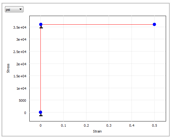
- Stress-Strain data:
| Strain | Stress – psi (kPa) |
|---|---|
| 0.0 | 0.0 |
| 0.0012 | 36,000 (248,211) |
| 0.5 | 36,000 (248,211) |
Constraints
- Frictionless Structural Constraint at each of the three flat surfaces
Load
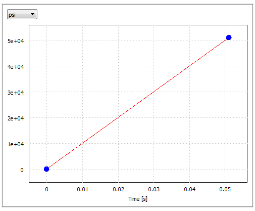
- Transient Pressure applied to interior spherical surface
- Multiplier Curve data (pressure increases 1,000 psi per millisecond):
| Time | Magnitude |
|---|---|
| 0.0 | 0.0 |
| 0.051 | 51,000 |
Theoretical Results
We consider solutions for the two limit cases as plasticity progresses from the inside surface to the outside surface:
- Case 1 (the beginning of plasticity) in which the inside surface just becomes plastic
- Case 2 (100% plastic penetration) in which the outside surface just becomes plastic
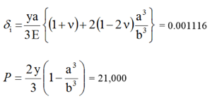
We calculate two variables—the radial displacement of the inside surface (δi) in inches and the applied pressure (P) in psi.
Case 1 (just plastic)
Case 2 (100% plastic)
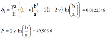
Where:
- y = 36,000 psi (yield stress of material)
- E = 30 x 106 psi (Young's modulus)
- ν = 0.29 (Poisson's ratio)
- a = 2 in (internal radius of sphere)
- b = 4 in (external radius of sphere)
Comparison of Results
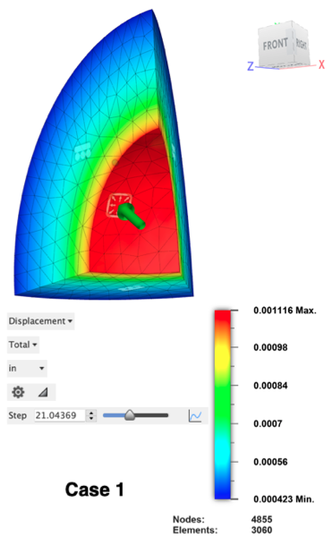
Fusion interpolates results between the solver's output increments. The pressure at which the model just achieves a 36,000 psi stress level can be determined using the 2D Chart of the maximum von Mises Stress results. As closely as possible, locate the point along the graph where the stress level first reaches 36,000 psi. Zoom in for better resolution when dragging the crosshair over the graph. To zoom, click and drag over the critical portion of the graph. The Case 1 step is approximately 21.04. The pressure increases 1,000 psi per step. Therefore, the applied pressure for Case 1 = 21.04 * 1,000 psi = 21,040 psi.
Display the Total Displacement results for the same step. Because of the geometry, all displacements are radial, and the maximum displacement occurs at the inside surface throughout the event.
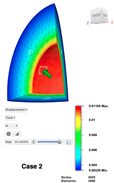
The pressure at which full plasticity is achieved is determined by looking at the 2D Chart of the maximum Total Displacement results. Determine the step at which the maximum displacement is on the verge of increasing rapidly. (Once full plasticity is achieved, there's nothing to prevent the rapid expansion of the sphere.) This condition occurs approximately at step 50.00. The displacement is increasing very gradually up to this step. From step 50.0001 upward, the rate of change is markedly increased. Therefore, the applied pressure for Case 2 = 50 * 1,000 psi = 50,000 psi., and the plot legend shows the corresponding displacement.
| Case Number | Applied Pressure (psi): | Radial Displacement (inches): | ||||
|---|---|---|---|---|---|---|
| Theory | Fusion | % Difference | Theory | Fusion | % Difference | |
| 1 | 21,000 | 21,040 | 0.19 % | 0.001116 | 0.001116 | -0.00 % |
| 2 | 49,906.6 | 50,000 | 0.19 % | 0.0122346 | 0.01185 | -3.14 % |
Reference
Chakrabarty, J., Theory of Plasticity, McGraw-Hill, New York, 1987, pages 307-311.