
Static stress 02: hemisphere with point loads
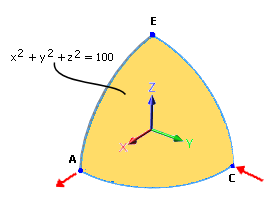
A hemisphere of radius 10 m with a uniform thickness of 40 mm is analyzed for a corner point displacement.
Case Description
An inwards force of 2,000 N in point C is applied, an outwards force of 2,000 N is applied at the point of interest of the displacement (point A). Both force vectors lie on lines that pass through the center point of the hemisphere, which is at the global origin.
Geometry
- Thickness = 40 mm
- Mean Radius = 10 m (to midplane of solid hemisphere)
Study Type
- Static Stress
Mesh Parameters
- Mesh Type = Solid, Tetrahedral
- Mesh Size = 10%, Model-based Size
- Element Order = Parabolic
- Adaptive Mesh Refinement: Enabled, with slider in High position
Material Properties
- Young's Modulus = 68.25 X 10⁵ MPa
- Poisson's Ratio (v) = 0.3
Constraints
- Frictionless Constraints at AE and CE edge faces
- Fully fixed at top vertex (Point E)
Loads
- Force 1 = 2,000 N in the X direction at Point A
- Force 2 = 2,000 N in the -Y direction at Point C
Comparison of Results
X displacement at point A (mm)
| NAFEMS (Shell) | Fusion (Solid) | % Difference |
|---|---|---|
| 185 | 185.1 | 0.05 % |
Reference
NAFEMS Publication Test No. LE3, The International Association for the Engineering Analysis Community, "NAFEMS Background To Benchmarks", G.A.O Davies, R.T. Fenner, R.W. Lewis, June, 1992.