Automated Modeling
Automated Modeling ![]() quickly generates design alternatives for connecting existing geometries in your design. Adding one of the alternatives to your design, creates a parametric, solid body that is editable using the Timeline.
quickly generates design alternatives for connecting existing geometries in your design. Adding one of the alternatives to your design, creates a parametric, solid body that is editable using the Timeline.
Using Automated Modeling speeds up the modeling process by suggesting different geometrical shapes that you can use to complete your design, or that you can use as inspiration for a final design.
Automated Modeling Overview (4:10)
The Automatic Modeling tool is now located in the Design workspace > Solid tab > Create panel.
Access
To access Automated Modeling, click Design workspace > Solid > Create > Automated Modeling ![]() .
.
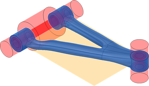
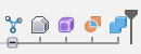
To get started, select two or more faces that you want to connect by generating a new solid body between them. Optionally, you can select solid bodies to avoid that represent areas where you want to avoid creating new geometry.
If the selected inputs are symmetrical, a symmetry plane is automatically created. This means that the new solid body will also be symmetrical about this plane.
Alternatives types
Automated Modeling generates two types of design alternatives:
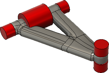
 Smooth Connections - the solid body that is connected to the selected faces using rounded connections (see 1).
  Sharp Connections - the solid body that is connected to the selected faces using sharper, edge-like connections (see 2).
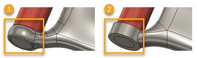
Both types are parametric so you can edit them in the Timeline.
Volume change
When alternatives are generated, you can change the volume of their shape.
To change the volume, select an alternative and use the volume slider or appropriate icons to adjust its shape.
If you want to:
- decrease the alternative, move the slider to the left or click Decrease
 .
. - increase the alternative, move the slider to the right or click Increase
 .
.
The volume of the alternative decreases or increases and you can track its change in real time on the canvas.
| MIN VOLUME | MAX VOLUME |
|---|---|
 |
 |
An example of the same alternative with minimum and maximum volume.
Timeline
When you add a design alternative to your design, an Automated Modeling ![]() feature group appears in the Timeline. You can double-click any feature in the Timeline to edit it directly.
feature group appears in the Timeline. You can double-click any feature in the Timeline to edit it directly.
The Automated Modeling ![]() feature group depends on the type of design alternative selected and looks as follows:
feature group depends on the type of design alternative selected and looks as follows:
Smooth Connections

Sharp Connections
In the timeline, you can find the following features:
 Base Feature (Sharp Connections only) - Creates solid bodies based on the selected faces that you want to connect. In the Base Feature contextual environment you can find the new solid bodies, called preserves, which are added in the Browser, nested in the Bodies folder.
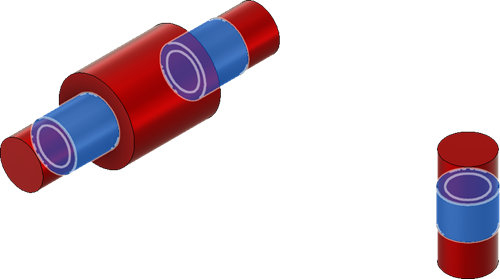
 Form Feature - Creates a new T-Spline body between the selected faces that you want to connect. You can use the Form tools to edit the history-free body by pushing and pulling on vertices, edges, and faces. In the Form contextual environment you can find a new T-Spline body which is added in the Browser, nested in the Bodies folder.
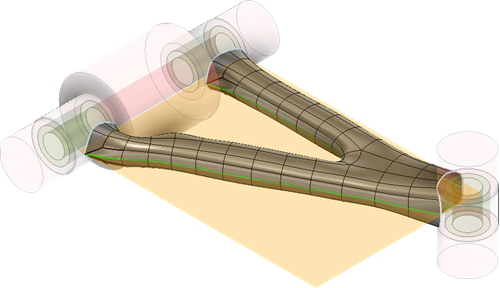
 Boundary Fill Feature (Sharp Connections only) - Creates a new solid body by joining or removing volumes using bounding volumes. These bounding volumes are formed by a new surface body and the solid bodies (preserves) created based on the selected faces that you want to connect.
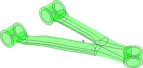
 Combine Feature - Combines a new solid body with the selected bodies (solid bodies on which you selected faces to connect and solid bodies you want to avoid) in the design by removing overlapping areas from the new solid body.