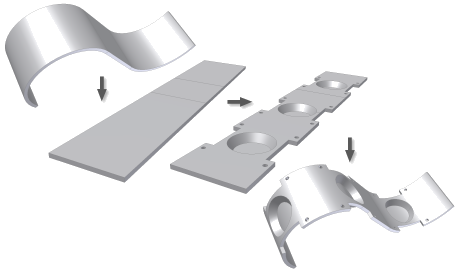
Certain sheet metal features are easier to create while the model is flat. These features can often cross bend areas in the finished part. The Unfold and Refold commands allow you to:
- Insert an unfold feature in the feature history of the part that flattens all or selected bends or rolls.
- Add features to the model in the flattened state.
- Insert a refold feature that allows any features added after the unfold feature to fold back to the original folded state.
You can unfold or refold sketches created on the folded or unfolded faces of a sheet metal part. Dimensions on these sketches can reference other features in a folded or unfolded state.
Unfolded compared to flat pattern
A folded model flattened by Unfold features is not equivalent to a flat pattern model. Using a model flattened by Unfold features for drawing creation is not recommended.
The flat pattern contains a wealth of bend and punch information useful for the creation of manufacturing drawings. Use the Flat Pattern command to obtain the flattened representation required for drawing creation. Differences include: bend up/down, punch depth, punch alternative representation and bend relief geometry.
Embossed feature deformation
Features modeled on or that come in contact with flattened bends deform when refolded. Features that protrude (up or down) from the sheet face deform relative to the neutral surface of the sheet face - not relative to the protruding geometry. To ensure that deformation matches shop floor results, limit protrusions to the value of THICKNESS whenever possible.
Sketches on unfolded bend
You can select existing flat faces or the flattened faces that result from unfolded bends or unrolled faces for sketch creation.
Merged face topology
To support the creation of features on the model in an unfolded state, changes were made to the way faces are merged.
 |
 |
|
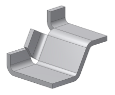
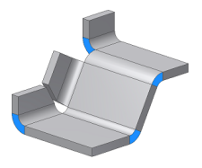
In releases before 2010, coplanar edge faces were merged into a single face. |
Beginning with 2010, coplanar edge faces are no longer merged into a single face. |
Sheet metal parts modeled before R2010 retain their merged coplanar edge faces when opened in R2010. Coplanar edge face topology splits into individual faces following the addition of an Unfold feature (shown in blue in the illustration).
Work geometry created from unfolded features
Options for defining work geometry increase with the addition of unfold and refold features. The following examples illustrate workplanes created using folded, unfolded and a mix of folded and unfolded features.
Created using folded geometry
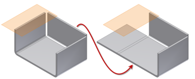
On the left in the previous illustration, a workplane has been created using folded model features. On the right side of the illustration, you see that the workplane remains in place when the parent feature is unfolded.
Created using unfolded geometry
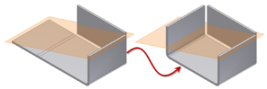
On the left in the previous illustration, a workplane has been created using unfolded model features. On the right side of the illustration, you see that the workplane remains in place when the parent feature is refolded.
Created using both folded and unfolded geometry
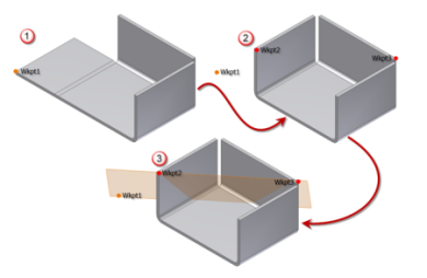
On the left in the previous illustration, a work point has been created using an unfolded model feature. On the right side of the illustration a second work point is created using the same vertex on the folded feature. A third work point is created on another folded feature and a workplane is created using the three work points. The bottom image illustrates that the workplane remains in place when the feature is unfolded or refolded.
Unfolded bends in multi-lump parts
Inventor allows the creation of sheet metal parts that contain separate solids (called “lumps”). Bends selected for an unfold operation must be part of the lump containing the unfold reference face.
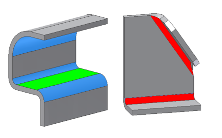
The illustration shows the selected unfold reference face in green. The bends shown in blue unfold using the selected reference face. The bends shown in red cannot unfold using the selected reference face.
Part transformation relative to origin
The Unfold and Refold commands allow manual selection of a stationary reference for the unfold and subsequent refold operation. This manual selection process allows a part to be transformed relative to the original orientation to the origin. Consider the following illustration showing four model states:
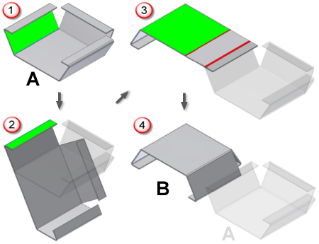
- In state 1, the part is shown in orientation “A” and the green face is selected as the stationary reference for an Unfold.
- A second Unfold is added using the green face shown in state 2.
- A Refold is applied to the two bends using the stationary face shown in green in state 3.
- Orientation “B” results as shown in state 4.
Refold features applied using either the Refold Feature context menu selection or the Automatic Selection Options method prevents this type of unwanted transformation.
For additional information on these Refold procedures please refer to Refold sheet metal features.