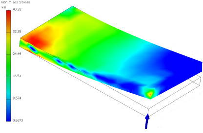
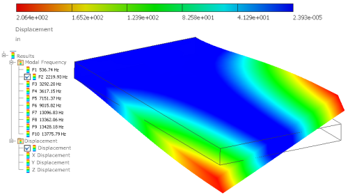
Physical displacements and stresses are calculated for parts or assemblies relative to the global coordinate system for the file. You view the results of these calculations through the Results node in the browser.
Within the Results browser node are the various result nodes. You can view Stress, Strain, Displacement, Safety Factor, and Contact Pressure results.
Additional commands for evaluating the results include:
- The ability to view the mesh overlaid on the results
- Minimum and maximum views that quickly show the locations of load extremes
- A deformation adjustment that allows you to visually enhance the effects of loads so you can more readily view the impact of loads
- Volume plots, both smooth shaded and contour
- Animation of the displacement
Static Analysis

For Static Stress Analysis, you can view:
- Strain results, including the strain tensor and the Principal and Equivalent strains
- Contact pressure (tractions)
- Displacement
- Stress
- Safety Factor
Fully defined material properties must be specified for the results plots to have meaningful content. You can use the Style and Standard Editor to review the properties of any material. The Style and Standard Editor is accessible from the Assign Materials dialog box.
Design constraints can be geometry based:
- Mass and volume
- A displacement component
- A stress component
- Other applicable field data
- Safety Factor
The stress state is calculated for a part or assemblies of parts. From the elasticity theory, the three-dimensional stress state on an infinitesimal volume of material at an arbitrary location contains Normal stresses and Shear stresses.
Three normal stresses, Stress XX, Stress YY, and Stress ZZ, and three shear stresses, Stress XY, Stress YZ, and Stress XZ, define the stress state. Tensile normal stresses are positive; compressive normal stresses are negative. Shear stresses are positive when their two defining positive axes rotate toward each other (using the right-hand rule).
Modal Analysis

Creating a modal analysis provides the means to calculate the natural frequencies of vibration for the number of frequencies specified. It includes frequencies that correspond to rigid body movements. In an unconstrained simulation, for example, the first six modes occur at 0Hz corresponding to the six rigid body movements. Design constraints can be geometry based or a frequency.
You can animate the deformed shape to show the modal shape associated with a particular frequency. The contours represent relative displacement of the part as it vibrates. Mode shape images are helpful in understanding how a part or an assembly vibrates, but do not represent actual displacements. To find all the mode shapes below a given frequency, be sure to determine the next two or three mode shapes.
The Compute Preloaded Modes option runs a structural static simulation first and determines the stresses, and then computes the modes, given the prestressed condition. Without the option selected, the program ignores any structural loads defined for the frequency simulation.