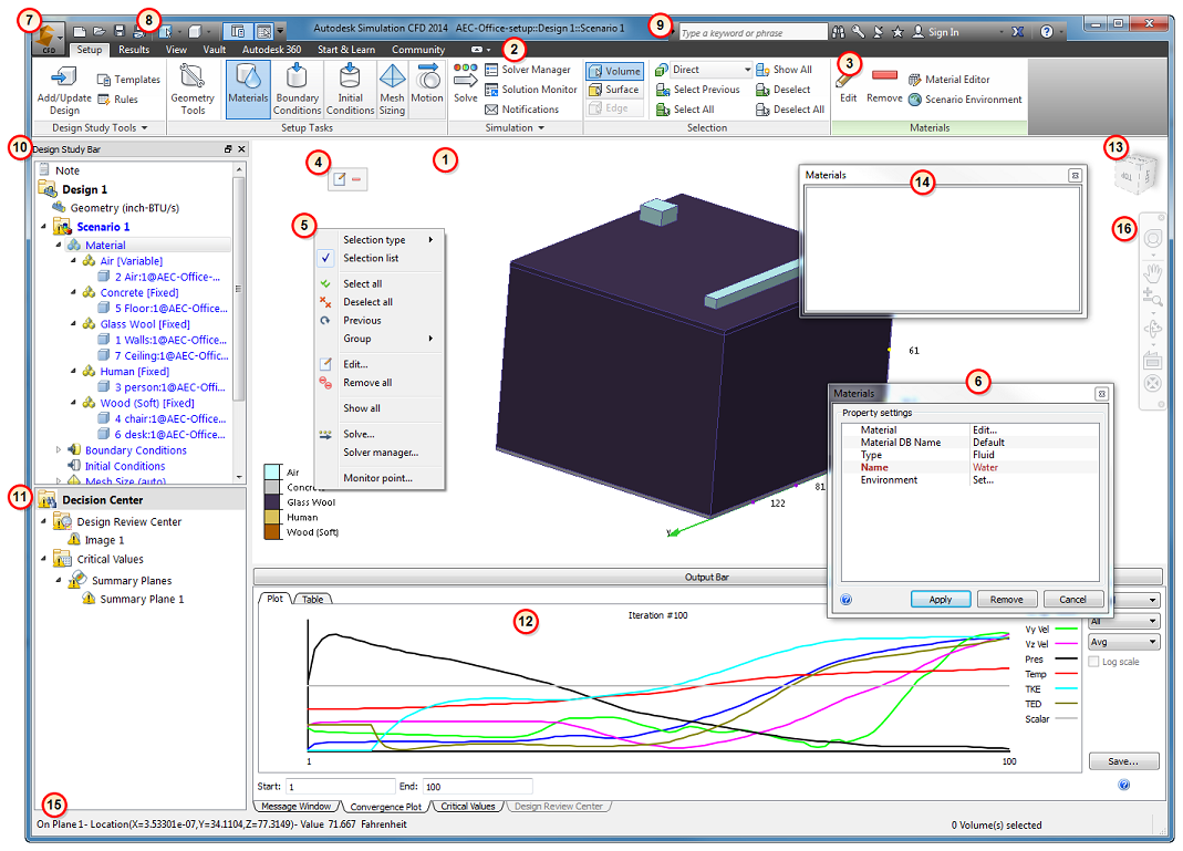
This is the default configuration of the Autodesk Simulation CFD User Interface:

Each part of the user interface serves an important purpose, and iIt is a good idea to familiarize yourself with these elements as they will help you to use Autodesk Simulation CFD efficiently.
User Interface Components
1. Graphics window
The Graphics window displays the model geometry, and contains several controls for interacting directly with the model. Navigate, select, and control entity visibility within the Graphics window.
These topics describe the specifics of interacting with the model:
2. Ribbon
Use the controls in the Ribbon for all stages of the simulation. The Ribbon is organized into tabs. Each tab is divided into panels. The commands on each panel are functionally related.
3. Context Panels
The primary task items in the Setup and Results tabs have an associated Context Panel that appears to the right of the ribbon. These panels update based on the active task, and provide easy access to commonly used controls associated with the task. Additionally, the active context panel is visible when either the View or Get Started tab is selected to provide continuous access to these controls.
For more about Context Panels...
4. Context Toolbars
Context toolbars provide convenient access to frequently-used functions specific to the current task. To open a context toolbar, click the left mouse button in the Graphics window.
For more about Context Toolbars...
5. Right-Click Menus
The right-click menus contain commonly used controls that are contextual to the current task. They provide convenient access to commands while allowing focus to be maintained directly on the model.
For more about the Right-Click menus...
6. Quick Edit Dialogs
Quick edit dialogs are the primary tool for specifying parameters and values for model set up and result extraction. Every task has a unique quick edit dialog that contains fields for task-specific settings. They are an essential workflow element of Autodesk Simulation CFD.
For more about Quick Edit Dialogs...
7. Application Menu
Use the Application Menu to manage files, set preferences, and to access recently saved design studies. To open the Application Menu, click the large icon in the top left corner.
For more about the Application Menu...
8. Quick Access Toolbar
The Quick Access toolbar contains several often-accessed controls such as file commands and appearance controls. The toolbar can be readily customized to suit personal preferences.
For more about the Quick Access Toolbar...
9. InfoCenter
The InfoCenter is your connection to many Autodesk® resources for information and news.
Use the InfoCenter to:
- Search for information through keywords (or by entering a phrase)
- Access subscription services through Subscription Center panel
- Access to product-related updates and announcements through Communication Center panel
- Access saved topics through Favorites panel
- Sign in to your Autodesk 360 account.
- Access Autodesk Exchange Apps
- Access topics in Help
For more about the Infocenter...
10. Design Study Bar
The Design Study Bar is a fully interactive tree-based tool for defining and managing all aspects of the Autodesk Simulation CFD process. The Design Study Bar follows a hierarchical structure that organizes the simulation process into three fundamental levels--Design Study, Design, and Scenario.
For more about the Design Study Bar...
11. Decision Center
The Decision Center is a simple yet powerful environment for comparing design alternatives. Use it to identify the design that satisfies your design objectives. The Decision Center is a key part of the results visualization process.
For more about the Decision Center...
12. Output Bar
The Output bar is the primary communication platform of Autodesk Simulation CFD. Status messages (and errors) are written to the Message window during several critical stages of the simulation process, including the following:
- Model load
- Simulation start
- Simulation completion
In addition to the Message Window, the Output bar contains tabs for the following actions:
- Monitor simulation progress with the Convergence Plot.
- Compare summary results with the Critical Values tab.
- Compare visual results with the Design Review Center tab.
For more about the Output Bar...
13. ViewCube
The Autodesk® ViewCube® navigation tool is a convenient, highly functional way to navigate your model and to adjust the viewpoint. You can use the ViewCube to quickly orient in any of 26 pre-set orientations, rotate the model about the Cartesian axes, and reset the model to its default orientation.
For more about the ViewCube...
14. Selection List
The Selection List displays items that have been selected in the Setup tasks. This is especially helpful for knowing exactly which items are selected.
In the Planes and Iso Surfaces Results tasks, the Selection List displays the list of existing planes or iso surfaces, respectively. In the Wall Calculator, Parts, and Points Results tasks, use the Selection List to interact with the controls of the current task.
To control the display of the Selection List, click the toggle in the Quick Access toolbar:

For more about the Selection List...
15. Status Bar
The Status bar displays values from probing results on surfaces and results planes.
16. Navigation Bar
The navigation toolbar is a collection of several tools for controlling model orientation and the view. It floats over and along one side of the graphics window. To activate a navigation action, click a button on the bar. Some of the buttons have additional tools in a sub-menu. To access these, click the small arrow below the button.
For more about the Navigation Bar...
Basic Workflows
A familiarity with the user interface tools is useful, but understanding how they work together is essential. There are several fundamental workflow paths within Autodesk Simulation CFD: Setup, Solve, Results Visualization, and Compare. Each uses one or more of the user interface tools. Click hereto learn more about these basic workflows.
Getting Help
There are several ways to learn more about functionality within the user interface. These methods include tooltips, the "F1" key, and in-context help buttons.