The Autodesk® Civil 3D® 2019.1 Update contains the following new features and enhancements.
Design Efficiency Updates
- Access rail-related commands from the Rail and Rail Alignment ribbon tabs.
- Access rail alignment creation, cant, crossover, and turnout commands, and rail subassemblies from the Rail ribbon tab.

- Access rail-related commands from the Rail Alignment contextual ribbon tab, which is displayed when you select a rail alignment in the drawing.

- The rail crossover and turnout features have been integrated into the Rail and Rail Alignment ribbon tabs. For more information about these features, see About Rail Crossovers and About Rail Turnouts.
- Access rail alignment creation, cant, crossover, and turnout commands, and rail subassemblies from the Rail ribbon tab.
- Access rail subassemblies from a tool palette that is dedicated to rail subassemblies.
On the Rail ribbon tab, click Subassemblies
 to open the New Rail tool palette.
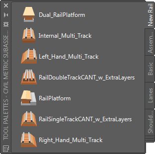
For more information, see New Rail Subassemblies.
- Create rail alignments using alignment creation commands which have rail-related settings selected by default. For more information, see
To Create a Rail Alignment and
To Create a Rail Alignment from Objects.
You can specify settings for these commands by editing the following command settings in the Toolspace Settings tree:

- Apply cant to an offset alignment.
You can use new options on the Offset Parameters tab of the Alignment Properties dialog box to specify whether to apply cant or superelevation to an offset alignment.

When you create an offset for a rail alignment, the offset alignment will have cant specified as its superelevation type by default, and when you select the offset alignment, cant-related commands are available in the Offset Alignment contextual ribbon tab.
For more information, see Offset Parameters Tab (Alignment Properties Dialog Box).
- Create and label best fit alignments and profiles using new options.
- Specify the spiral type to create when creating a best fit alignment.
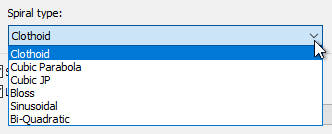
For more information, see Create Best Fit Alignment Dialog Box.
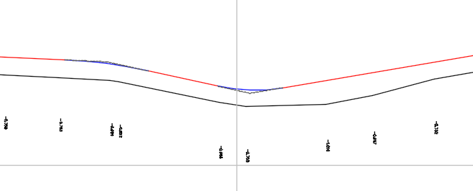
- Create best fit profiles that are at or above the elevations of the selected input data. Use new options to control whether the resulting best fit profile elevations will be above the input data, or whether the elevations can be above and below the input data.

For more information, see Create Best Fit Profile Dialog Box.
In the following illustration, the best fit profile is drawn above the input data (a surface profile).
- Add labels to best fit alignments and profiles. Options are now available when creating best fit alignments and profiles to insert labels in the drawing to show the offset between the source data and the resulting best fit alignment or profile.
For more information, see Create Best Fit Alignment Dialog Box and Create Best Fit Profile Dialog Box.
- Specify the spiral type to create when creating a best fit alignment.
- Specify the maximum rate of change for superelevation cross slope for an alignment.

For more information, see Edit Feature Settings - Alignment Dialog Box.
- Create a floating vertical tangent in a profile by specifying a grade and a length.
The specified grade is held if you grip edit the length of this type of tangent.

For more information, see To Add Floating Tangents to Profiles.
- Use new report stylesheets to control the appearance and content in reports for rehab corridors.
Stylesheet Features Example Report Rehab-All - with color.xsl - At stations where the corrected slope does not match the ideal slope, the Corrected Slope column is shaded yellow.
- If the difference between the existing slope and the ideal slope exceeds the slope tolerance, the Difference column is shaded red.

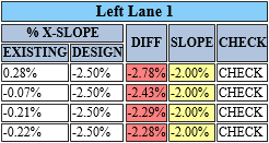
AL DOT Cross Slope.xsl - This report has a Check column which contains either Match or Check:
- Match: The slope matches the desired design slope.
- Check: The slope does not match the desired design slope.
- At stations where Check is reported, the Slope column is shaded yellow and the Diff column is shaded red.
Mill and Level - with color.xsl - This stylesheet produces a report with the following differences from the existing millandlevel.xsl stylesheet:
- Mill and level are displayed in separate columns.
- Color ranges are displayed in the output.

AL DOT Mill and Level.xsl - Mill and level are displayed in separate columns.
- Units are not included in the table cells.
- A single control point is reported (instead of control points on both left and right sides). The control point that is reported is the point where the least amount of milling is required.
- A single edge point is reported on each side (instead of two points on each side).
- The average end area of the level material is reported for each station and a running total is provided.

For information about how to select these stylesheets, see To Generate Rehab Corridor Reports.
- Specify the type of connection points on structures to use when laying out pipe networks.
When you lay out a pipe network, you can select which type of connection point to use: the structure insertion point, the default connection point (the first connection point that is defined for a structure), or the closest connection point to the cursor.

You can also reset the connection points after laying out the pipe network.
The following part types in the Generic Drainage with Pipe Connections - Imperial and Generic Drainage with Pipe Connections - Metric catalogs have been updated to have new connection points and grips:
- Rectangular Underground Structures: Pipe connection points have been added at the inside center of each wall.
- Eccentric Cylindrical Structures: A single pipe connection point has been added to the center of the underground barrel.
- Rectangular Grates: Move grips have been added to the back left corner, back center, and back right corner of each rectangular grate. Rotation grips have been added to the back center of each rectangular grate.
For more information, see About Pipe Network Connection Points and To Reset Pipe Network Connection Points.
You can add connection points to custom parts by using the Infrastructure Parts Shape Utilities tools in Autodesk® Inventor®. For more information, see To add reference points.
Production Efficiency Updates
- Reference sample line groups into drawings using data shortcuts.
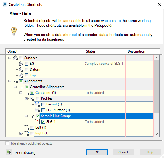
When you create a data shortcut for a sample line group, a data shortcut to the parent alignment is also created. For more information, see To Work With Data Shortcuts.
When you create the data references, you can specify which sample lines in the sample line group to reference and which data sources to sample. For more information, see To Create Sample Line Group References.
Note: Please note that the ability to create sample line group data references is not currently integrated into Autodesk® Vault and therefore this feature is unavailable at this time for organizations using Vault for Civil 3D project data management. - Synchronization notifications are displayed for data references only if a data-referenced object is changed in the source drawing and the drawing is saved, and are not displayed if something unrelated to the object occurs in the drawing.
Collaboration and Data Exchange Updates
- Publish surfaces to Autodesk® BIM 360™ Document Management for use in Autodesk® Revit®.
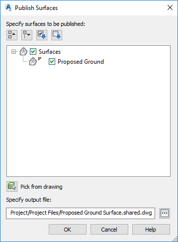
Select the surfaces to publish and specify a location in a BIM 360 project.
For more information, see To Publish Surfaces to Autodesk BIM 360 to Reference into an Autodesk Revit Model.
- Use updated LandXML import and export features when importing or exporting data.
- Import and export rail cant data using the LandXML import and export commands. When you import or export an alignment that has cant data defined for it, the cant data is included. Alignments with cant data are imported into
Autodesk Civil 3D as rail alignment types.
For more information about importing and exporting LandXML, see To Import LandXML Drawing Data and To Export Drawing Data to LandXML.
- Import breaklines as either feature lines or as 3D polylines when importing surface data from LandXML files. Use a new property in the LandXML Settings to control which type of object to create.
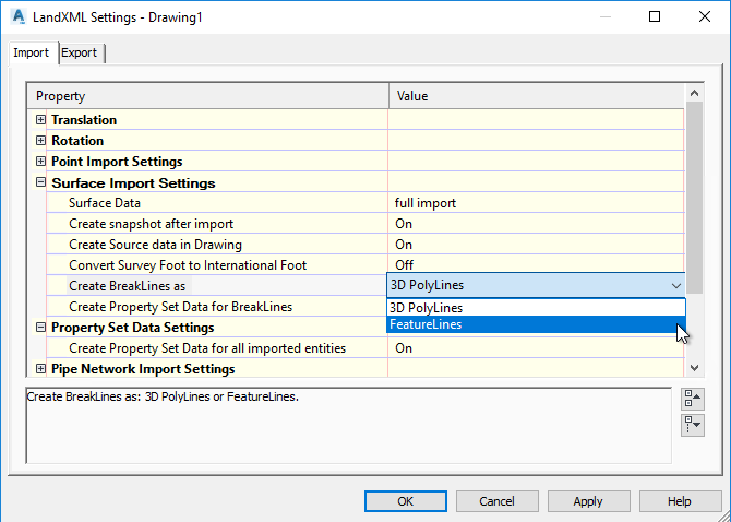
For more information, see Import Tab (LandXML Settings Dialog Box).
- Specify whether property set definitions are created and applied when surface data is imported from a LandXML file. You can view this property set data in the AutoCAD Properties Palette and in tooltips.

For more information, see To Import LandXML Drawing Data and Import Tab (LandXML Settings Dialog Box).
- Import and export rail cant data using the LandXML import and export commands. When you import or export an alignment that has cant data defined for it, the cant data is included. Alignments with cant data are imported into
Autodesk Civil 3D as rail alignment types.
New Features in Autodesk® AutoCAD® 2019.1
- The Shared Views feature in the AutoCAD 2019.1 Update includes support for property sets on AutoCAD objects such as 3D solids.
Note: The AutoCAD 2019.1 Update is a separate install and is an installation prerequisite for Autodesk Civil 3D 2019.1.