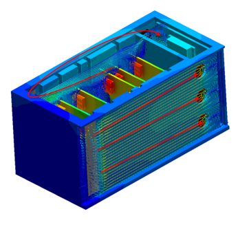
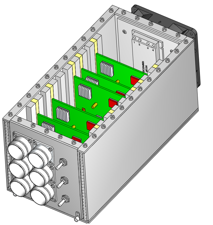
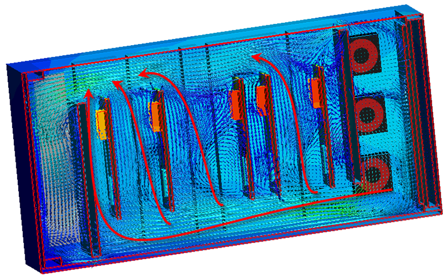
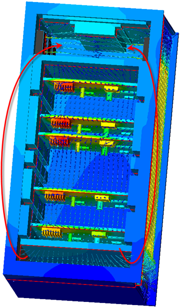
Internal Forced Cooling: Sealed
A fan circulates air contained within the enclosure. Because it cannot enter or leave, it is essential that circulating air efficiently removes heat from critical components, and transfers heat to the casing. Conduction paths between critical devices and the casing are also very important for effective cooling.
Application Examples

- Telecommunications devices
- Control modules
- Devices in harsh environments
Modeling Strategy

- Simplify the geometry to remove extraneous features. Simplify or rebuild sheet metal parts to remove detail that is not relevant to the simulation.
- The model must contain an air volume within the device. This is a consideration because the physical model probably does not contain one. Autodesk® CFD automatically creates an internal volume if the geometric model is "water tight." If not, modify the CAD model to close any gaps or use the Void Fill tool to create the volume on the Autodesk® CFD model.
- To ensure enough space between the boundary conditions and the internal flow, it may be necessary to extend the openings in the CAD model. (This is only relevant if the device has openings.)
- The device enclosure often has little effect on the temperature distribution. Consider suppressing from the CAD model or from the mesh.
Materials
- The properties of air should be constant.
- Assign Air, and set the Environment setting to Fixed.
- For very thin enclosures, the heat transfer is largely dominated by thermal conduction instead of convection. In certain applications, it is possible to accurately simulate the heat transfer without having to solve for the flow. A solid material called Solid Air, in the Default database, has the thermal properties of air. For more about using the Solid air material...
- Use material devices to simulate objects such as baffles, internal fans, printed circuit boards, compact thermal models, and thermal electric devices. For more about using material devices...
- Use aluminum or other appropriate material for housing parts.
Boundary Conditions
Heat transfer boundary conditions should always be applied if the objective is to learn the temperature distribution. (These can be omitted if the objective is to assess only the flow.) A temperature must be assigned somewhere on the model. Because there is not an inlet on a sealed device, assign a temperature using one of the following methods:
Temperature boundary condition on an exterior surface
Apply a Total Heat Generation boundary condition on components that dissipate heat. Note that power is evenly dissipated over the entire volume.
To simulate heat transfer to the surroundings, apply a Film Coefficient boundary condition to the external surfaces. The value depends on the air that surrounds the physical device:
- If the air is still, use a value of 5 W/m²K.
- If the air is moving, use a value of 20 W/m²K.
- Use a Reference Temperature = ambient temperature.
Mesh
A basic guideline for a high-quality analysis model is that the mesh distribution be sufficient to resolve the flow and temperature gradients efficiently. In regions where the flow circulates or experiences large gradients (such as in wakes, vortices, and separation regions), a finer mesh is required.
For most models, use Automatic Sizing to define the mesh distribution. It may be necessary to locally refine the mesh on geometric features that are highly detailed. For more information about Mesh Autosizing and model preparation...
In some cases, it may be necessary to adjust the Minimum Refinement Length to reduce their effect on the overall mesh count.
To locally refine the mesh in high-gradient flow regions:
- Adjust the mesh distribution on geometric volumes and surfaces.
- If there are no appropriate geometric features in a particular region, create a mesh refinement region:
- Add one or more volumes in the CAD model.
- Create a Refinement Region from the Meshing task.
Running
On the Physics tab of the Solve dialog:
Flow = On
Heat Transfer = On
Automatic Forced Convection = On
Turbulence:
- Most forced-flow analyses are turbulent, and the default model, K-Epsilon, is recommended.
- Flow in devices with a "puller" fan may be laminar. To select Laminar on the Turbulence dialog:
- Open the Solve dialog, click the Physics tab, and click the Turbulence button. Select Laminar.
Autodesk® CFD stops the solution either when the specified number of iterations have elapsed or when the solution is converged, whichever comes first. To ensure the analysis is not stopped before converging, set the Iterations to Run to 500. Most analyses converge within 200-300 iterations so 500 should provide an adequate margin.
Results Extraction
Flow Distribution

Component Temperatures:

- Use Results Planes and Iso Surfaces to visualize the flow in and around the fixture.
- Use Particle traces to visualize air movement.
- Display temperature directly on parts and use Results Parts to extract quantitative temperature data.
- Use the Decision Center to compare results from multiple scenarios. Save summary images and create summary items, and evaluate the results in the Critical Values table.
For more general information, use the extensive collection of results visualization tools to extract flow and thermal results.
Troubleshooting
Oscillating convergence, as shown by a "saw tooth" convergence plot, is a problem that occasionally occurs when internal fans are defined with a fan curve:

This is caused when the operating point of the system varies significantly from one iteration to the next, and the operating point on the fan curve varies with it. The intersection of the fan curve and the system curve is the operating curve of the fan. If the solution changes too rapidly from one iteration to the next, this point develops a repeating overshoot/undershoot, and the "saw tooth" convergence plot is the result.
To fix this issue:
- On the Control tab of the Solve dialog, click the Solution control button.
- Uncheck the Enable button in the Intelligent solution control section.
- Drag the Velocities and Pressure sliders from 0.5 to 0.2.
- Check the Enable button in the Intelligent solution control section again. Click OK.
- Continue the analysis.
This change slows the solution of the velocity and pressure variables, and prevents the operating point from varying do dramatically:

Things to Avoid
- Do not include geometric detail that is irrelevant to the flow and heat transfer. Remove features such as sheet metal bends, screws, and wires.
- Flow and heat transfer can be solved simultaneously, but this usually takes longer than solving them in series (either manually or with Automatic Forced Convection).
- The only time it is necessary to solve flow and heat transfer together is if the air properties vary with temperature.