Work with the probes, tools, and settings that are used in the inspection.
The role and contents of the tab depends on the type of measuring device specified in the ribbon .
Depending on the machine type and protocol, you use the machine tab to:
- not connected to a measuring device — specify probe components for the program simulator. The Machine tab is disabled for disconnected manual CMMs.
- connected with device protocol or I++ client-tool protocol — show the calibration status of probes, and manage the calibrations of each probe. For CNC machines, you can also specify and manage racks.
- connected with I++ protocol — model probes for the simulator, and select probes and positions. You must first calibrate the probes in the I++ server.
- OMV Machines — specify the measuring device, probe, and probe tools. You can also simulate the inspection.
Probe View
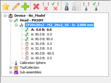
The Probe View displays the details of the measuring device to be used when creating inspections for CNC machines and manual CMMs.
Probe View
When the document is connected to the measuring device, the view displays the device's current set-up. When the document is not connected to the measuring device, the view can be configured to use any machine set-up.
The Probe View includes the:
- Probe View toolbar
- Machine Model area (for CNC machines).
- Probe Head area
- Probe Tool area
- Probe Positions area (when using an indexable head)
- Sub-assemblies area (for CNC machines)
When the document is connected to a CMM using the device or I++ Client Tool protocol, it also displays:
- Icons indicating whether the probe and probe position are calibrated
 , or uncalibrated
 . If
Use form tolerance setting is selected, an additional
. If
Use form tolerance setting is selected, an additional
 icon indicates whether the probe or position is calibrated, but outside the specified form tolerance.
- The last calibration date of the selected probe or position; the effective or nominal diameter of the stylus, and the calibration status of the selected probe or position.
Probe View Toolbar
Specify and calibrate probes for CNC machines or manual CMMs for the document, and calibrate the probe assemblies.
The options depend on whether the document is connected to the measuring device, and the connection protocol.
- Activate
 — Change the active probe or the active probe position of the new probe or probe position selected in the
Tool Collection list.
— Change the active probe or the active probe position of the new probe or probe position selected in the
Tool Collection list.
The new probe is shown in bold at the top of the list.
- Edit
 — Edit the selected probe tool assembly. The
Probe Tool Assembly dialog is displayed.
— Edit the selected probe tool assembly. The
Probe Tool Assembly dialog is displayed.
- Add
 — Create new probe positions.
-
Delete
 — Delete the selected item.
-
Delete Uncalibrated Positions
 — Delete all uncalibrated probe positions in the selected item.
-
Delete All Positions
 — Delete all probe positions in the selected item.
-
Calibrate
 — Calibrate the selected item:
- Full calibration mode, theProbe Calibration Wizard is displayed.
- Simple calibration mode, the
Calibration and Positions dialog is displayed. Use it to calibrate the probe by taking a single point.
Note: To change the calibration mode, use the Calibration page of the Options dialog.
-
Calibrate Using Nominal Offset
 — Use the nominal offset of the item to calibrate the probe head or the probe tool.
If you selected the:
- probe head, the Probe Head Mounting Direction dialog is displayed;
- probe tool or a tool orientation and the probe head is not calibrated, the Probe Head Mounting Direction dialog is displayed.
- probe tool or a tool orientation and the probe head is calibrated, the item is marked as calibrated.
Note: This button is available only when Simple calibration mode is selected in the Calibration page of the Options dialog.
-
Calibrate Uncalibrated Positions
 — Calibrate all uncalibrated probe positions in the document.
The Batch Probe Positions Calibration dialog is displayed. Click Start to calibrate each uncalibrated position.
- Calibrate All Positions
 — Calibrate all probe positions in the document.
To sort the probe positions, right-click a probe and choose an option from the context menu. Select:
- Reset to clear the selected sort options.
- Take calibration into account to list all calibrated orientations followed by all uncalibrated orientations.
- A angle first to sort the orientations by the size of their A-angles.
- B angle first to sort the orientations by the size of their B-angles.
- Ascending order to sort the angles in ascending order of size.
- Descending order to sort the angles in descending order of size.
When the document is connected to the measuring device using the I++ Server protocol, the Probe View lists the server's probes. You can select the active probe and probe position using the Probe View toolbar, but you must define and calibrate the probes within the I++Server.