Stormwater Controls (SWC) often vary between projects, locations and clients. Flexibility of design facilities is crucial. The flow routing through a SWC is described in Analysis of Stormwater Controls.
The list of the various types of SWC is shown below, with images of these systems for easy reference.
Using Object Templates, any one of these Stormwater Controls types can be saved in order to use it elsewhere in the same design or in a completely different assessment.
SWC can be drawn graphically on the plan using three types of outlines; Circular, Rectangular and Free form. A default outline is selected when the SWC is first added to the plan, but these can be modified using the right-click menu.
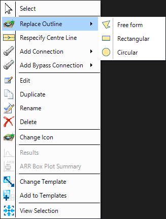
The overall outline is the top area, where a SWC has sloping sides or a different base area – this will be shown with a dashed outline.
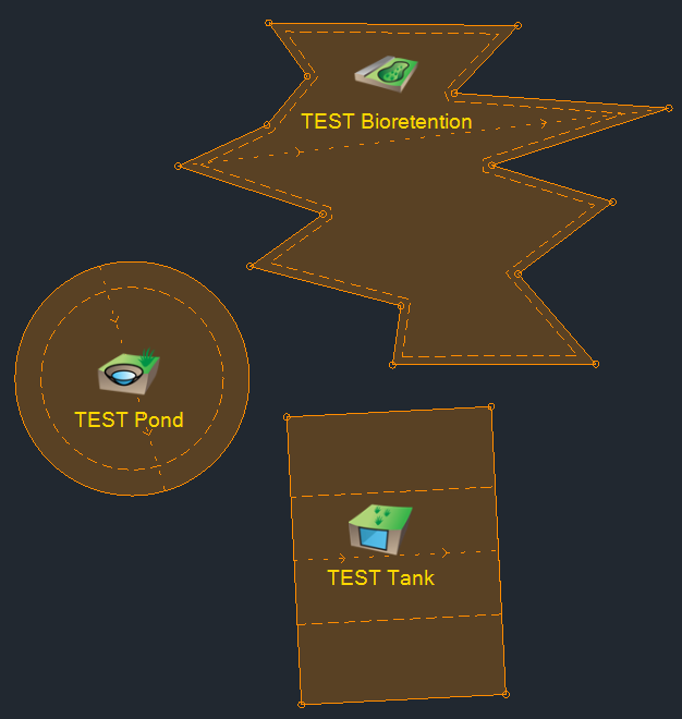
A centre line is calculated for each outline type, which gives an indication of the direction of travel to allow a longitudinal slope to be applied, but this can be modified using the right-click menu. The centre line is calculated for each line type in the following way:
Circular
The last mouse click to indicate the size of the circle denotes the direction of travel from the centre.
For old files with a surface, the highest cover level is determined around the outline perimeter, and this is the start of the centre line. Without a surface, the centre line is drawn from left to right through the centre.
Rectangular
From the centre of the rectangle from left to right, including for old files.
Free form
The longest distance between all the coordinates is determined, and the direction of travel is either calculated from:
- The surface (when present), where the highest cover level is the start of the centre line
- From the winding of the outline, where the first centre line coordinate reached is the top of the centre line.
For old files, the same rules apply when calculating the centre line.
If a SWC is added during an Add train operation, the centre line direction is dictated by this operation and any changes to the outline will maintain this centre line, unless the outline is deleted.