Assemblies overview
An Assembly is a collection of components that function as a single design in Fusion.
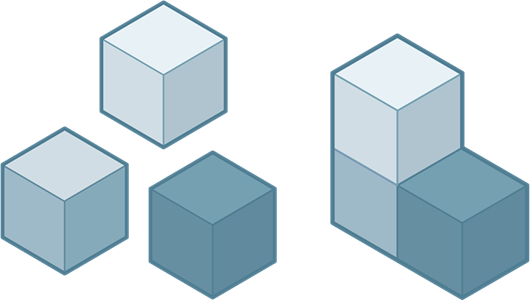
Assembly workflows let you create individual components (parts) and combine them into larger, functional units (assemblies). This is a holistic process that considers the individual components and their interactions to create a well-functioning and manufacturable product.
You can create assemblies that leverage a variety of different strategies, based on the design's intent. You may:
- Create assemblies that consist of all internal components, all external components, or a mixture of both component types.
- Define the structure and relationships in the assembly at the beginning of a project or as you evolve the design.
- Take a top-down or bottom-up approach to the entire assembly, or vary your approach for specific components and subassemblies.
- Work alone on a design or collaborate with other project members.
- Collaborate concurrently or asynchronously with other project members.
Here are a few ways to create an assembly:
Bottom-up approach
You can model parts and consider their geometry, materials, and specific manufacturing processes individually. Then insert them into an Assembly Design and position parts relative to one another to form an assembly.
- Create a Part Design and model some geometry.
- Create an Assembly Design and insert the Part Design as an external component.
- Create more Part Designs and insert them in to the Assembly Design as external components.
- In the Assembly design, define Relationships between the components.
Top-down approach
Alternatively, you can design parts in context of the assembly so you can consider how all the parts fit together to form a complete product.
- Create an Assembly Design.
- In the Assembly Design:
- Create a new component and select Part to create a stand alone Part Design and insert it here as an external component.
- Use Edit in place to model geometry in the Part Design.
- Create more Part Designs as external components in place.
- Define Relationships between the external components to create the assembly.
Typically, you will use a blend of these workflows but these workflows provide an overview of different schools of thought when it comes to design intent.
External components
When you create assemblies with external components, it makes it easier to:
- Collaborate with teammates.
- Reuse Part designs in other Assembly designs.
- Consume data for individual components in downstream data workflows like BOM and PLM.
- Simplify the feature timeline and reduce compute time for larger assemblies.
Hybrid design workflow
When you create an assembly design and decide that you need to create internal components in the design, you can switch the design's workflow to a Hybrid Assembly Design.
In a Hybrid Design, the toolbar displays the modeling tabs (including Solid, Surface, Form, Sheet Metal, and Mesh) so you create internal components, model geometry, insert external components, and define relationships to create an assembly.
If you intend to create create internal components in a Hybrid design, it is best to:
- Use the New Component tool to create components early in the design process, before you start creating geometry.
- Activate the component you want to work on, then create sketches and bodies inside the component they belong to from the start.
This workflow helps you maintain a clean, organized parametric history for each component, and sets up components in a way that makes them easy to reuse in other designs.
Instead of converting an Assembly design type to Hybrid, you can enable modeling to create internal components.
Distributed designs
A distributed design is a design with one or more external components referenced into the assembly.
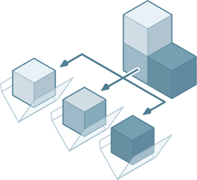
Distributed designs enable multiple project members to edit different components in the assembly at the same time. As each project member edits components in context, the entire assembly updates to reflect their changes. You can see who is editing each component, update components as project members save their changes, and ensure everyone is always working with the latest version of each component in the assembly.
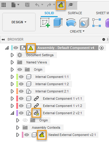
Updates in the assembly
An Out-Of-Date icon ![]() displays in the following places when a project member saves changes to a design or an external component in the assembly:
displays in the following places when a project member saves changes to a design or an external component in the assembly:
- In the the Application bar
- Next to the default component in the Browser
- Next to an external component in the Browser
If a subcomponent nested within an external component is out-of-date, the Subcomponent Out-Of-Date icon ![]() displays next to the parent external component.
displays next to the parent external component.
You can update the active design, external components, and derived features that are out-of-date, and out-of-sync assembly contexts all at once or individually.
Position and connect components
When you insert a design as an external component into an Assembly for the first time, it is automatically Ground to parent and is rigidly assembled to the default root component. All other designs you insert after that are not assembled to the root and can move freely with six degrees of freedom in the Assembly design. You can use positioning features and create Relationships to position these components relative to each other, limit their degrees of freedom, and define motion.
See Relationships.
Strategy for creating relationships in complex assemblies
Group components into subassemblies to easily reuse components in more than one assembly and to simplify the assembly process for complex assemblies with many components.
First, create several smaller assemblies in separate assembly designs and define relationships between components as needed, then insert the designs as subassemblies in a larger assembly design. This approach lets you position the subassembly as a single unit in upstream assemblies.