Generate a Multi-Axis Feature Construction additive toolpath
This feature is part of an extension. Extensions are a flexible way to access additional capabilities in Fusion. Learn more.
After you have prepared the design, created an additive setup, and copied or created a depositing tool, generate a multi-axis additive toolpath.
On the Manufacture workspace toolbar, click Additive > Multi-Axis > Feature Construction
 .
.The Feature Construction dialog opens.
On the Tool tab, click Select to pick a depositing tool.
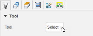 Note: Any values associated with the selected depositing tool (stored in the Tool Library), such as Bead Width, Layer Thickness, and the various feedrates, now show in the dialog.
(Optional) If you have multiple presets of process parameters, for example, for different materials, machines, or applications, choose a Preset.
On the Geometry tab, specify the base surface on which to deposit the features:
Choose a Base Type to identify the geometry of the base surface.
Note: The settings available in the Passes tab change depending on the base type.On the canvas, click the face of the base surface.
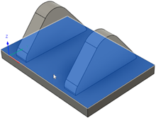
Specify the features you want to deposit:
In the Feature Selection group, ensure that Feature is active.

On the canvas, click the features.
To select a feature, you can click a body or the faces of a body.
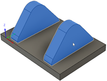 Note: The features must be separate bodies from the base surface.
(Optional) By default, the Z axis of the work coordinate system (WCS) defined in the setup sets the orientation of the depositing tool. If you want to override this, on the Multi-axis tab, select the Tool Orientation checkbox and choose a Tool Orientation option.
For example, if the base surface is based on a planar surface, it must be perpendicular to the Z axis.
On the Passes tab, set parameters to define the pattern of the toolpath passes.
To deposit a wall that traces the outline of the features, select the Perimeter checkbox.
To deposit within the perimeter walls, select the Infill checkbox.

Example of one layer of infills only (left), perimeters only (center), and infills and perimeters (right).
Note: You must select the Perimeter checkbox or the Infill checkbox or both.(Optional) To override the value defined in the depositing tool's preset, enter a different Layer Thickness. This value specifies the distance between each successive layer of passes.
(Optional) To keep the head of the depositing tool at a certain angle during deposition, in the Multi-Axis tab, select the Tool Axis checkbox, and then enter a Forward Tilt and a Sideways Tilt angle relative to the surface normal.
In the Linking tab, choose a Retraction Policy to control how the depositing tool moves when it is not depositing the bead of melted material.
Click OK.
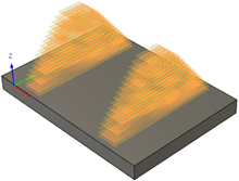
The additive toolpath is generated, and the in-process stock is displayed.
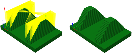
Example of the in-process stock with (left) and without (right) the link moves.
(Optional) To make the additive toolpath easier to see, press F8 to hide the in-process stock, and, in the Browser, click
 to hide the features.
You can now animate the deposition and simulate the additive toolpath before post processing.