Preview a machine’s movements in the Machine Builder
If you have linked a machine model to a machine definition, you can validate the movement of the CNC machine by jogging axes to ensure that the simulation behaves realistically. First ensure that you have adjusted axis directions, and assigned components and defined attachment points, so that the machine model accurately represents the physical configuration of your CNC machine.
Open the machine model in the Machine Builder:
On the Manufacture workspace toolbar, on any tab, click Manage > Machine Library
 .
.In the Machine Library, navigate to one of the My Machines subfolders and select the machine definition.
Tip: Ensure that the machine definition has a linked machine model, indicating it is machine simulation-ready.
On the toolbar, click
 to open the machine definition’s machine model in the Machine Builder contextual environment.
On the Machine Builder contextual environment's toolbar, click Preview Machine Movements
 .
.Jog the axis as needed:
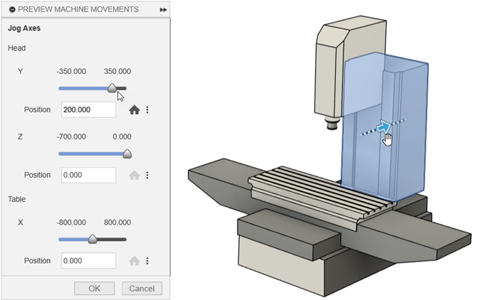
In the Preview Machine Movements dialog, drag the axis slider or enter a value in the Position box, or
On the canvas, click and drag the axis.
 Tip: Entering a Position, or moving the axis directly on the canvas, can be useful when the desired zero point is outside the axis' current range limits.
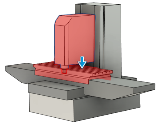
 Note: If you jog axes such that they collide into one another, the colliding axes are highlighted red on the canvas.
(Optional) Click:
Home
 to return the axis to its home position.
Position
 > Save as Zero to set the current position of the axis as the new zero point.Note: Changing the zero point does not change the value of the home position or the values of the minimum and maximum range limits. However, it does affect where the models appear on the canvas at these positions. This is because these values are measured from the zero point. You can adjust the minimum and maximum range limits in the Kinematics tab of the Machine Definition dialog.
Position
 > Reset to Default Zero to reset the position of the axis to the original zero point regardless of any previously saved home position or zero position.
Position
 > Save as Minimum Limit or Save as Maximum Limit to set the current position of the axis as the minimum or maximum value that the axis can reach, as measured from the zero position.
Position
 > Save as Home to set a new home position for the axis.
(Optional) To see a preview of a ball-nose-style tool at the tool attachment point, enter a Diameter and Length.
The tool preview can help assess the suitability of different-sized tools when the machine is at different positions.