Workflow: Using the Machine Builder
Use the Machine Builder to view and configure a machine model for a CNC machine. By adjusting axis directions, assigning components, and defining attachment points, you can accurately represent the different aspects of your machine. And then interactively jog the axes to visually verify that the machine model moves in a manner consistent with your physical CNC machine.
Ensure that the machine model is linked to a machine definition.
Open the machine model in the Machine Builder:
On the Manufacture workspace toolbar, on any tab, click Manage > Machine Library
 .
.In the Machine Library, navigate to one of the My Machines subfolders and select the machine definition.
Tip: Ensure that the machine definition has a linked machine model, indicating it is machine simulation-ready.
On the toolbar, click
 to open the machine definition’s machine model in the Machine Builder contextual environment.
(Optional) To access and change the settings of the machine definition linked to the machine model, click Edit Machine Definition
 .
.Click Move Components
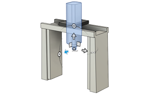
 to align the axes of the machine model with the coordinate system to ensure accurate representation.
Click Set Up Machine Model
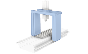
 to assign components and define attachment points in the machine model to ensure that the machine model accurately represents the physical configuration of your CNC machine.
Click Preview Machine Movements
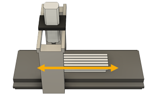
 to interactively jog the axes, visually verifying that the machine model moves as intended.
(Optional) To align the machine model with the ViewCube orientation, click Orient Machine Model
 .
.Click Finish
 to save the design file containing the machine model and close the Machine Builder.
If you select a machine definition with a linked machine model ![]() in a setup, the machine model is displayed on the canvas during simulation. This enables you to see how the physical CNC machine will move when running NC code.
in a setup, the machine model is displayed on the canvas during simulation. This enables you to see how the physical CNC machine will move when running NC code.