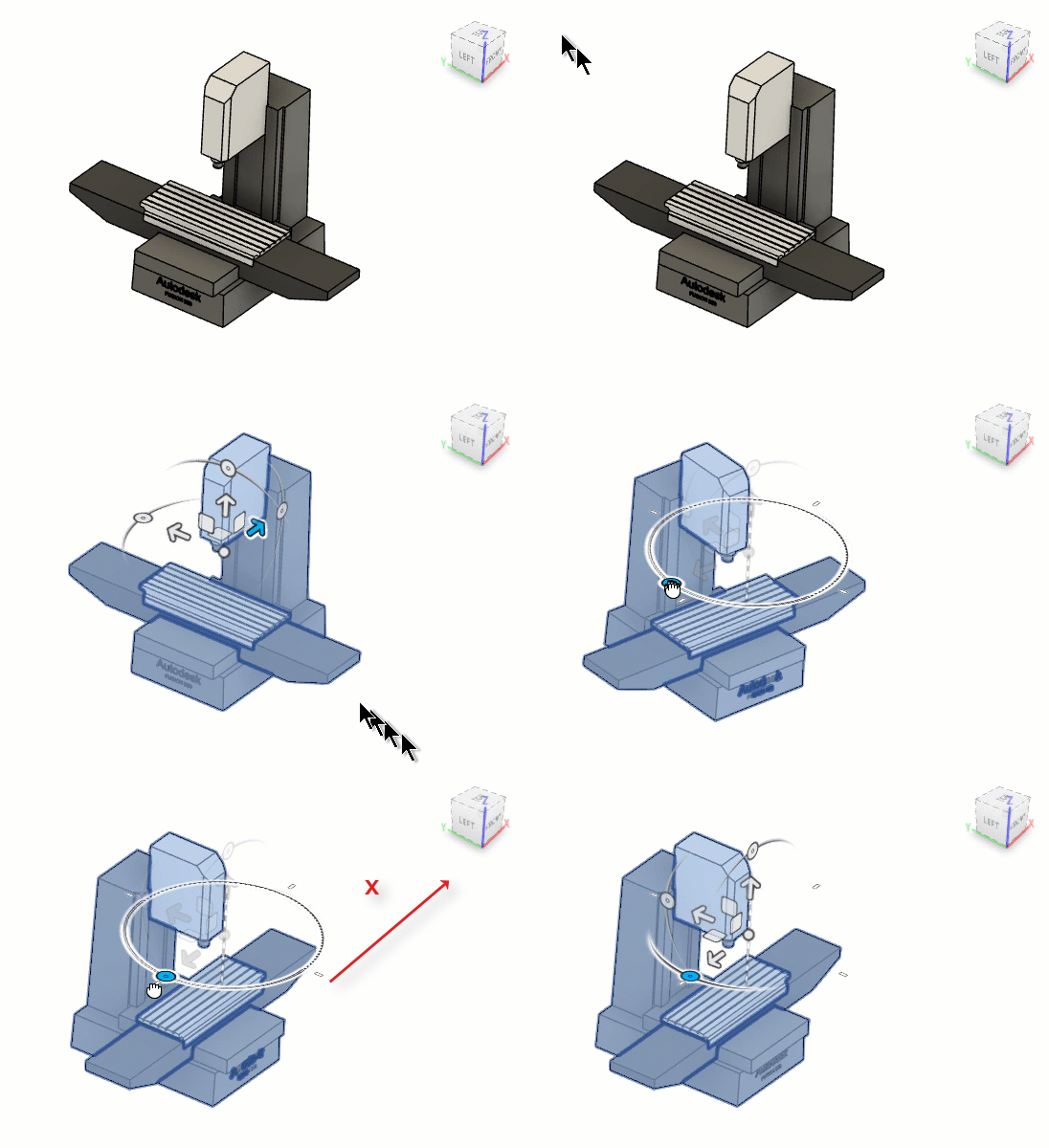
Move components in the Machine Builder
If you have linked a machine model to a machine definition, you can adjust axis directions to ensure that the machine model matches the physical configuration of your CNC machine.
Open the machine model in the Machine Builder:
On the Manufacture workspace toolbar, on any tab, click Manage > Machine Library
 .
.In the Machine Library, navigate to one of the My Machines subfolders and select the machine definition.
Tip: Ensure that the machine definition has a linked machine model, indicating it is machine simulation-ready.
On the toolbar, click
 to open the machine definition’s machine model in the Machine Builder contextual environment.
On the Machine Builder contextual environment's toolbar, click Move Components

On the canvas, select the component you want to move.
Use the manipulator to move and rotate the component as needed.
 Tip: Select the entire machine model and rotate it 90 degrees to match the ViewCube orientation.
Within the Machine Builder, you can now assign components and define attachment points to ensure that the machine model accurately represents the physical configuration of your CNC machine, and then validate the movement of the CNC machine by jogging axes to ensure that the simulation behaves realistically.