Set up a machine model in the Machine Builder
If you have linked a machine model to a machine definition, you can assign components and define attachment points, ensuring that the machine model accurately reflects the physical configuration of your CNC machine. First ensure that you have adjusted axis directions so the machine model matches the physical configuration of your CNC machine.
Open the machine model in the Machine Builder:
On the Manufacture workspace toolbar, on any tab, click Manage > Machine Library
 .
.In the Machine Library, navigate to one of the My Machines subfolders and select the machine definition.
Tip: Ensure that the machine definition has a linked machine model, indicating it is machine simulation-ready.
On the toolbar, click
 to open the machine definition’s machine model in the Machine Builder contextual environment.
On the Machine Builder contextual environment's toolbar, click Set Up Machine Model
 .
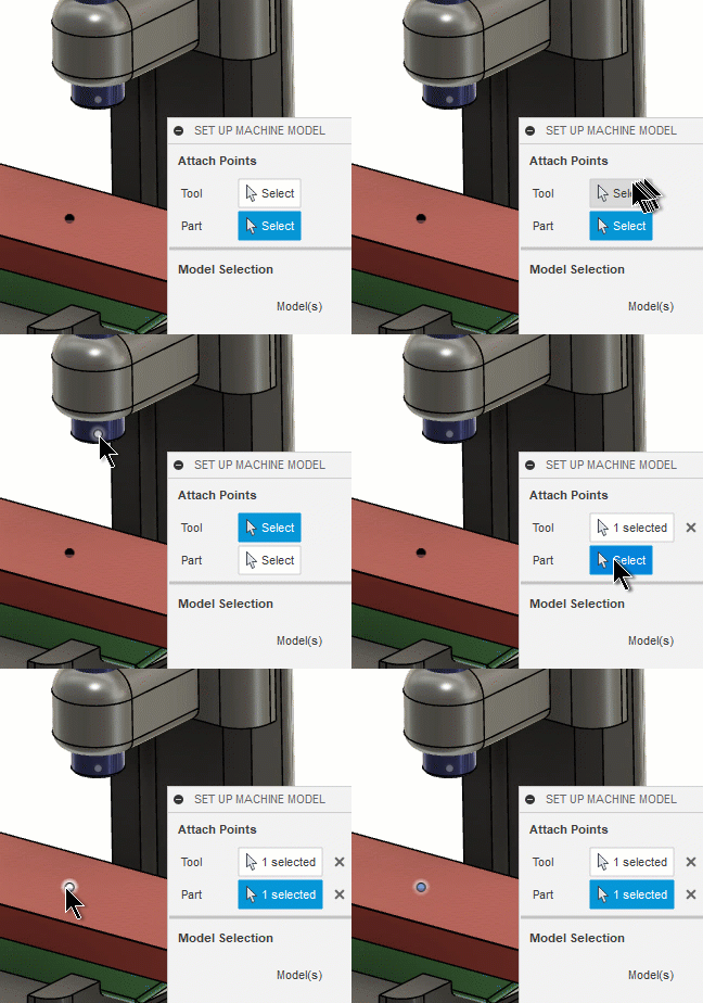
.In the Set Up Machine Model dialog, in the Attach Points group, for Tool, ensure that Select is active, then, on the canvas, click the location point for the tool.

For Part, ensure that Select is active, then, on the canvas, click the location point for the part, vise, or fixture.
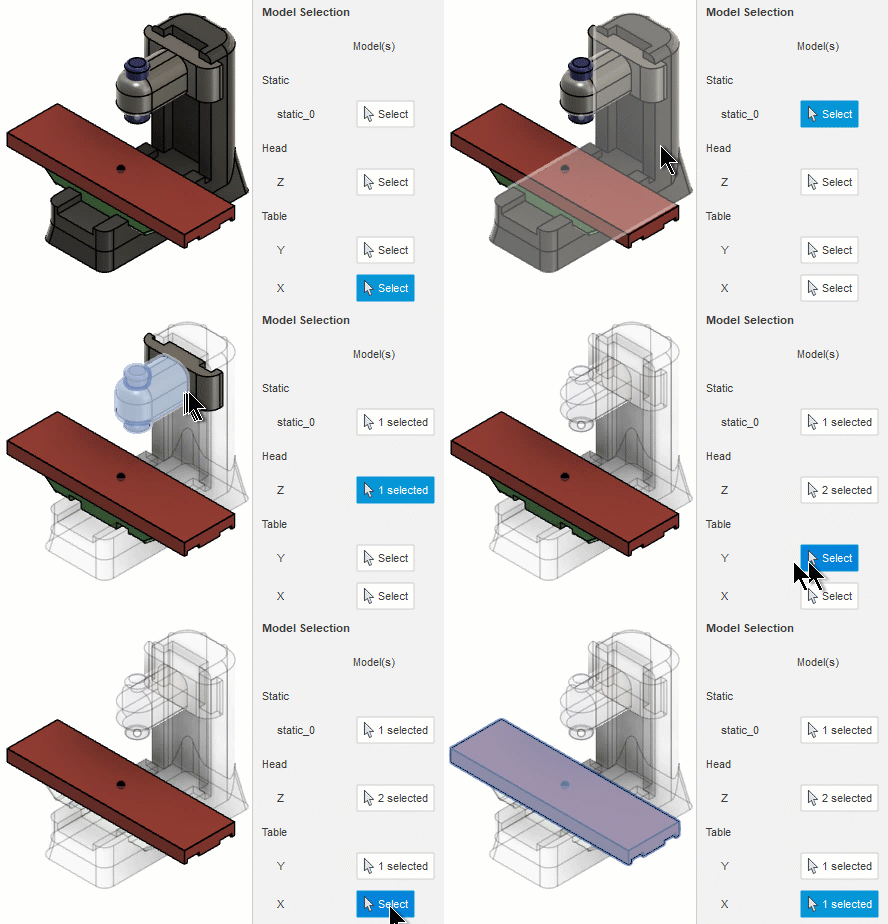
In the Model Selection group, for Static, ensure that Select is active, then, on the canvas, select the components that represent the nonmovable base of the machine.
This is the component to which all the other components will be attached.
For Head, ensure that Select is active, then, on the canvas, select the components that represent the axis.
For Table, ensure that Select is active, then, on the canvas, select the components that represent the axis.

Within the Machine Builder, you can now validate the movement of the CNC machine by jogging axes to ensure that the simulation behaves realistically.