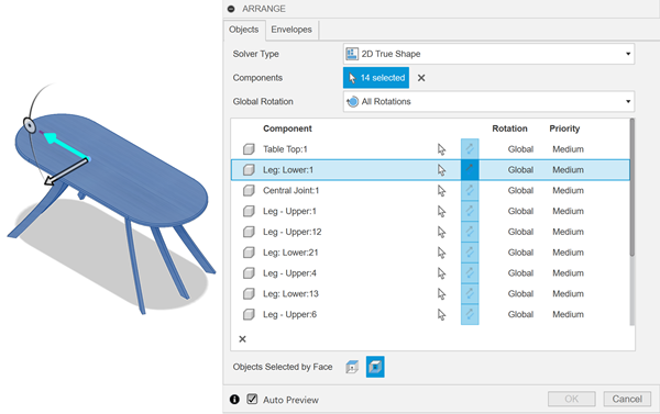
Select components to arrange
This feature is part of an extension. Extensions are a flexible way to access additional capabilities in Fusion. Learn more.
As with standard Arrange, while in the Edit Manufacturing Model contextual environment, click Manufacture > Modify > Arrange.
The Arrange dialog opens.
In the Objects tab, select a Solver Type:
- 2D Rectangular - arranges components on a flat surface, each in its own rectangular region.
- 2D True Shape - arranges components on a flat surface in such a way as to minimize cutout area.
- 3D Arrange - arranges components inside a defined 3D volume.
Select components to arrange, either from the canvas, or in the Browser.

Specify the Global Rotation to determine in what ways the components can be rotated within the arrangement.
(Optional) To keep the original set of components in the same location and use their copies for the arrangement, select the Create Copies checkbox.
Specify the Global Quantity to determine the number of complete sets of components to arrange (2D Solver Types only).
(Optional) You can specify individual values for particular components in the selection table on the Objects tab (2D Solver Types only):
- Set an individual quantity by overwriting the Global value
- Force a component to be aligned with the X axis of the sheet
- Flip the component's face orientation on the sheet
- Set an individual rotation constraint
- Determine component priority
- Specify Filler components by selecting the Filler checkbox (2D True Shape Solver Type only).
Note: As you set a component as a filler, the component quantity is automatically set to 999. You can override this value by entering the desired value in the component's Quantity box.(Optional) To allow fitting smaller components inside holes within larger ones, select the Allow Part-in-Part checkbox (2D True Shape Solver Type only).
Select an area to arrange on
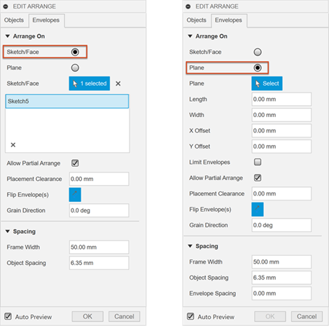
In the Arrange dialog, click the Envelopes tab.
Select the type of area that you want to arrange on.
Sketch/Face - Creates an envelope or a set of envelopes from a selection of sketches or planar faces.
Plane - Generates a set of envelopes on a selected plane.
The type of area you choose determines what the remaining controls are in the dialog.

Depending on the setting made in the previous step, select the sketch, face or plane in the model to arrange the components on.
If you selected Plane, specify the Length, Width, and Height (3D Arrange Solver Type only) to determine the dimensions of each of the envelopes along the X, Y and Z axis.
Adjust other arrangement settings as needed.
Arrangement values:
- X Offset and Y Offset (planes only) - Sets the point in which the first envelope is created relative to the model origin.
- Limit Envelopes (planes only) - Lets you specify a fixed number of envelopes to arrange the parts on. When deselected, the number of envelopes used is determined by however many are needed to complete the arrangement. If you select Arrange by Material, the limit is applied to each material. For example, if you have two materials and set the envelope limit to 1, the result will be two envelopes, one for each material.
- Number of Envelopes (planes only) - Specifies the number of envelopes to use for the arrangement. If the specified number or size of the envelopes does not accommodate all the selected components, you can select Allow Partial Arrange to get a result. If Allow Partial Arrange is switched off, you can change the Number of Envelopes value to assess whether you have enough stock to fit all the components. If you select Arrange by Material, objects made of different materials will be placed in separate envelopes.
- Arrange by Material (planes only) - Allows components made of different materials to automatically be placed on separate envelopes. For each material represented in the selection set, a dedicated envelope is created along the Y axis. Each envelope in the arrangement has a corresponding physical material assigned to it, matching the material of the components that it includes.
- Allow Partial Arrange - Allows a partial arrangement result when there is not enough space on the envelopes to fit all components. Components are arranged until all the available space is used up. The components that were not included in the partial arrangement are highlighted in the components list. If the envelope size increases, the arrangement recalculates to include the components that did not previously fit in the arrangement.
- Placement Clearance - Places components at a specified Z height above the envelope. A value of zero places the components directly on the envelope.
- Flip Envelope(s) (2D Solver Types only) - Flips the envelope along with the components arranged on it to show either their downward- or upward-facing side.
- Grain Direction (2D Solver Types only) - Sets the direction of the grain on the envelope, which is measured from the X-axis of the envelope and in the counterclockwise direction. All components on the envelope change their orientation to align with the direction of the grain.
Spacing values:
- Frame Width - Specifies the width of an empty border within the arrangement area.
- Object Spacing - Specifies the distance between one object in an arrangement and its surrounding components.
- Envelope Spacing (planes only, 2D Solver Types only) - Specifies the distance between envelopes.
- Ceiling Clearance (3D Arrangement Solver Type only) - Specifies the clearance distance from the top of the 3D envelope to the top of the arrangement.
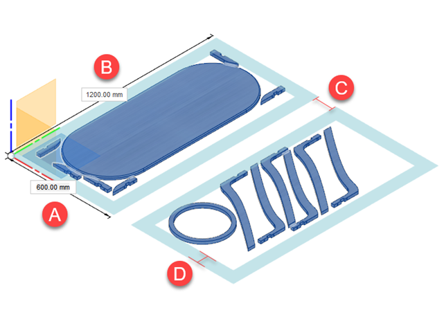
For example, this arrangement uses the following values across multiple envelopes:
- A. Length - 600 mm
- B. Width - 1,200 mm
- C. Envelope Spacing - 100 mm
- D. Frame Width - 70 mm
