Geometric tolerancing symbols
In the Drawing workspace in Fusion, you can use the tools in the Symbols panel on the toolbar to add GD&T symbols to sheets in a drawing as you document your design.
You can use the following tools to add GD&T symbols to a sheet:
- Surface Texture

- Feature Control Frame

- Datum Identifier

- Welding

- Taper and Slope

- Edge Symbol

- Sketch Symbol

Surface Texture
The Surface Texture tool attaches surface textures to objects, existing dimensions, or existing feature control frame symbols.
Feature Control Frame
The Feature Control Frame tool creates a rectangular frame that is divided into two or more sections. It can be attached to notes, linear, diameter, radius and angular dimensions and the text of these annotations.
Datum Identifier
The Datum Identifier tool creates a datum identifier symbol to identify a datum feature for a feature control frame symbol.
Welding
The Welding tool creates a welding symbol.
Taper and Slope
The Taper and Slope tool creates a taper and slope symbol.
Edge Symbol
The Edge Symbol tool creates an edge symbol. Edge symbols specify requirements around the processing and finishing of specific edges, and they indicate the type of edge and it’s details with defined or undefined size and direction.
Sketch Symbol
The Sketch Symbol tool lets you create and insert customized sketch symbols in a drawing or template. You can import the sketch symbols from another drawing or template files. Attach sketch symbols with leaders and automatic Alpha or numeric counters, ideal for flag notes, inspection bubbles, custom balloons, or ISO/DIN 5459 style datum target symbols.
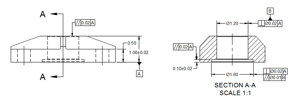
ASME Standard
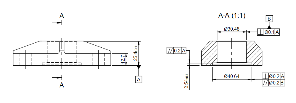
ISO Standard
To add geometric tolerancing to a drawing, you can generate feature control frames, datum identifiers, and surface textures and attach them to an object. After creating a GD&T symbol, it remains associated with the assigned object.
The drafting standard (ASME or ISO) defines the behavior and characteristics of each symbol. Specify the drafting standard before you create the drawing. Some symbol properties and characteristics, including the special characters displayed within the Symbol palette, are defined by the drafting standard in use.
You can attach feature control frames to components of the model and to existing dimensions. Datum IDs and surface textures can be attached to components, dimensions, and feature control frames.
Tips
Reassociate disassociated symbols to edges and surfaces by clicking the Annotation Monitor badge
 and clicking the Reassociate button or anywhere within the blue highlighted area.
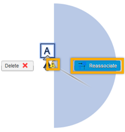
Fusion remembers the Surface Texture, Feature Control Frame, Welding, and Taper and Slope symbols’ last used settings. Once you place the symbol with all the desired settings filled out, you can continue adding the symbol without having to fill out the same settings.
If you don’t want to use the last used settings, click the Reset button. It clears out all the previously used settings.
If you want to reuse an already used symbol and its settings, but you have cleared out all the previously used settings, or you placed a symbol with different settings than the ones you want to reuse, double-click the symbol you want to reuse. This opens the Symbol dialog and makes these settings the last used ones. After you close the dialog, you can continue adding the symbol without having to fill out the same settings.