Activity 5: Create obstacle geometry for the center pin
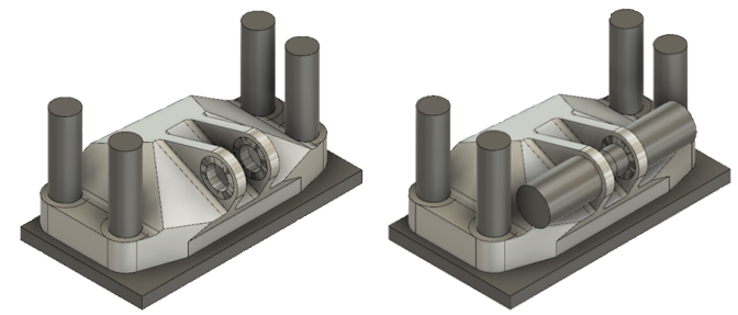
In this activity, you create obstacle geometry to ensure the correct functioning of the center pin. This aerospace assembly is fastened to another assembly with a pin through the center. Similarly to the bolt holes, you create obstacles to ensure that not only does the pin fit in the center of the holes, but also that it can be installed and removed for maintenance of the bracket.
Prerequisites
- Activity 4 is complete.
Steps
Create obstacle geometry that enables installation and removal of the pin, starting at the outside face of one of the center pin preserves, and extending away by 45mm.
Note: Ensure that Auto project geometry on active sketch plane is turned on in the Design section of Preferences (default setting), to capture the edges of the preserves.Note: Create the geometry as a new body to separate the preserves from the obstacles.- Hide Body1, the GE bracket, by clicking the Visible icon
 .
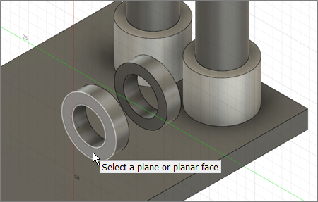
. - On the Edit Model Solid tab, click Create > Create Sketch
 , then click on the face of the closer center pin preserve geometry.
- On the Edit Model Solid tab, click Create > Extrude
 , then click on the center circle and the surrounding circle.
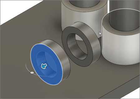
- Click on the blue arrow, and drag it away from the preserve geometry to 45mm.
- Select New Body as the operation in the Extrude dialog.
- Click OK to close the Extrude dialog.
Note: Body 14 is now visible in the Browser.
- Hide Body1, the GE bracket, by clicking the Visible icon
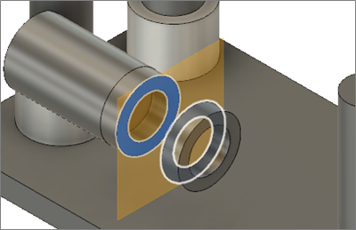
Create a Midplane between the two center preserves, about which you can create a mirror image of the obstacle geometry.
- Click the top right corner of the ViewCube to rotate the model.
- Turn on visibility for the previous sketch by clicking the Visible icon
 next to Sketch3, or the latest sketch in your Browser tree.
 - On the Edit Model Solid tab, click Construct > Midplane
 .
. - Click on the two faces on the interior of the bracket, then click OK.
Join new geometry for the pin to the obstacle geometry you created in step 1, starting at the end that meets the center pin preserve, and ending at the midplane.
- On the Edit Model Solid tab, click Create > Extrude
 .
. - Click on the small circle in the sketch, then hover over the midplane and click on it when it turns white.
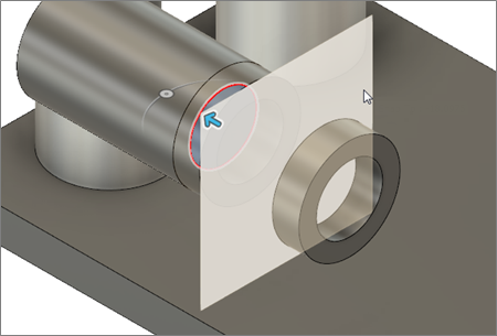
- Hide Body3, the preserve geometry that surrounds the body you are creating, by clicking the Visible icon
 (Model Components > Bodies > Body3).
Note: On your model, this might be Body4, depending on which order you selected the faces when you created the preserve geometry. - Select Join as the Operation in the Extrude dialog.
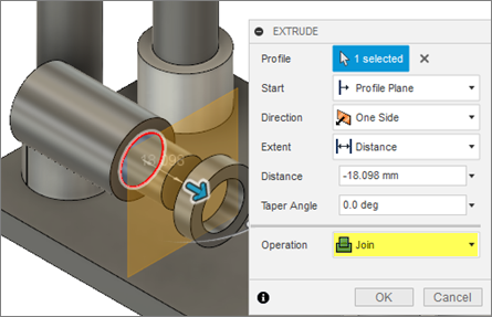
- Click OK to close the Extrude dialog.
Note: Body14 should still be visible in the Browser. If it is no longer visible, undo the Extrude operation, and repeat the steps above, making sure that you hide Body3 before you click OK.
- On the Edit Model Solid tab, click Create > Extrude
Create a mirror image of the obstacle geometry you created, about the midplane, to complete the center pin obstacle geometry.
- Make Body3 visible again, by clicking the Hidden icon
 .
. - In the Create panel, click Mirror
 to open the Mirror dialog.
 - Select Bodies as the Pattern Type.
- Select Body14.
- In the Mirror dialog, click Select associated with Mirror Plane, then click the midplane.
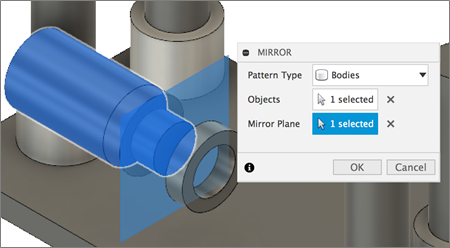
- Click OK to close the Mirror dialog and create the mirror geometry.
Note: Body15 is visible in the Browser. - Hide the midplane by clicking the Visible icon
 next to Construction.
 - Make the GE bracket model visible by clicking the Hidden icon
 next to Body1.
 - Click Home View to return the model to its original orientation.
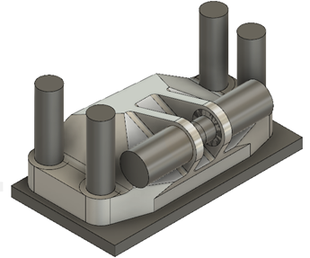
- Make Body3 visible again, by clicking the Hidden icon
Activity 5 summary
In this activity, you created obstacle geometry for the center pin. You started by creating a new body on one side of a center pin preserve. You created a Midplane, then joined additional to the new body, starting at the end adjacent to the center pin preserve and extending to the Midplane. You then created a mirror image of the geometry about the midplane, to complete the creation of the obstacle geometry.
You accomplished these tasks using the following tools:
- Create Sketch
- Extrude
- Construct Midplane
- Mirror