Activity 4: Create obstacle geometry for the bolt holes
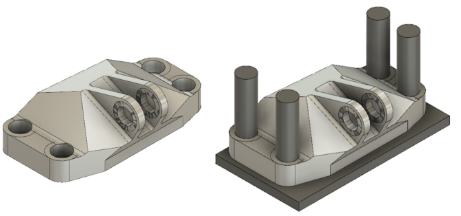
In this activity, you create geometry to act as obstacles for the bolt holes, using the Fluid Volume tool. When you define a generative design geometry, you need to consider how the solution is used, installed, maintained, and how it interacts as part of an assembly. All these considerations might be areas to set up obstacles. In this activity, you put a patch surface on the top and bottom of the bolt holes, then use the Fluid Volume tool to create a watertight solid of the voids you want to maintain.
Prerequisites
- Activity 3 is complete.
Steps
Create a box primitive geometry, that is just larger than the bracket, to prevent geometry from being created past the bottom face of the bracket.
Note: This box primitive acts as an obstacle to ensure that the bracket maintains the proper mounting surface.- On the Edit Model Solid tab, click Create > Box
 .
. - Click Front on the ViewCube, then bottom to rotate the bracket so the bottom face is facing you.
- Click the bottom face of the model, then draw a square around the model.
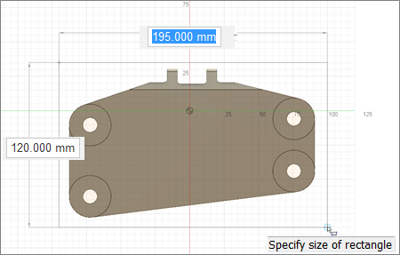
- Type 190, then press Enter on your keyboard.
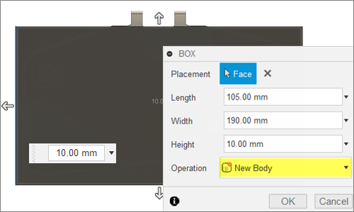
- Enter 105 as the width, and 10 for the height.
- Select New Body as the operation, then click OK to close the Box dialog.
- Click Home View to return the model to its original orientation.
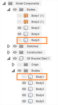
Note: A new body, Body5, is now visible in the Browser.
- On the Edit Model Solid tab, click Create > Box
Create a patch on each side of the four bolt holes.
- Hide Body1 by clicking the Visible icon
 .
. - On the Edit Model Surface tab, click Create > Patch
 .
. - Click on the inside top edge of a bolt hole, then right click and select OK.
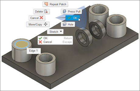
- Click on the inside top edge of the next bolt hole, right click and select Repeat Patch, then right click and select OK.
- Repeat step 2.d. for the remaining bolt holes.
- Rotate the model so you can see the bottom, by clicking on the bottom corner of the central axis of the ViewCube.
- Hide the box you created earlier by clicking the Visible icon
 next to Body5 (Model Components>Bodies>Body5).
 - Repeat step 2.d. to patch the bottom of the four bolt holes.
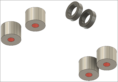
- Hide Body1 by clicking the Visible icon
Create the solid bodies of the voids.
- Click Home View to return the model to its original orientation.
- On the Edit Model Solid tab, click Create > Fluid Volume
 to create a watertight solid of the internal void.
 - Band select two of the bolt hole geometries.
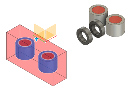
- Select Internal as the volume in the Fluid Volume dialog.
- Rotate the model by clicking the top right corner of the ViewCube, to bring the other two bolt hole preserves to the front.
- Band select the second two bolt hole preserves.
- Click OK to close the Fluid Volume dialog.
- Click Home view to return the model to its original orientation.
Extrude the hole geometries upwards to 65mm to create the final obstacle geometry for the bolt holes.
Note: This step is necessary, because there is nothing to prevent the solutions from growing above the new solids. If this were to occur, you wouldn't be able to install the bolts or get a tool in to tighten them.- Select bodies 6-13.
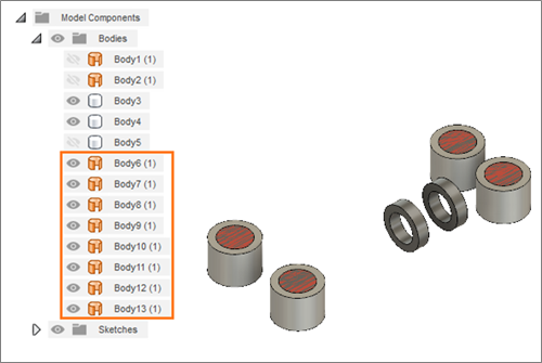
- Right click and select Remove to remove them from the Browser.
Note: The solid bodies of the voids are in the Component geometry in the Browser. - On the Edit Model Solid tab, click Create > Extrude
 .
. - Click the top of all four bolt holes.
- Click on the blue arrow and drag it upwards to 65mm.
- Right click and select OK.
- Show the model and the box by clicking the Hidden icon
 next to Body1 and Body5.
- Click Home View to return the model to its original orientation.
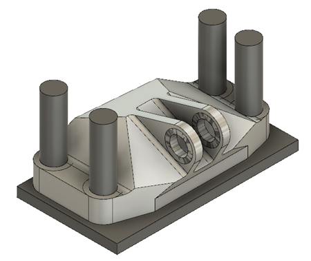
- Select bodies 6-13.
Activity 4 summary
In this activity, you created obstacle geometry for the bolt holes. You started by patching the top and bottom surfaces of the bolt holes. You then used the Fluid Volume tool to create a watertight solid of the voids. Finally, you extruded the solids to create obstacle geometry in the bolt holes and the area above them.
You accomplished these tasks using the following tools:
- Create Box
- Patch
- Fluid Volume
- Extrude