
Weld Surface Mapping
The workflow for mapping weld surface data from your Moldflow model to your structural model is the same as what is described in the Mapping Results topic. The only additional requirement is that the .ws3 file exists in the same directory as the .sdy file during import into Advanced Material Exchange. During import, Advanced Material Exchange reads, translates, and stores the weld surface data in the .sif file. As a result, the .ws3 file is only required during import, not during the structural analysis.
Minimum Projection
The process of transferring weld surface data consists of mapping the field of strength reduction factors from the Moldflow results to the corresponding Gauss point in the structural model. By default, this is achieved with the Minimum Projection method. The Minimum Projection algorithm searches for all of the weld surface points contained in a given structural element. If any points are found, the lowest strength reduction factor in that element is applied to all Gauss points within the element. The Minimum Projection method is useful if you have a coarse structural mesh.
Shepard's Algorithm
The alternative to the Minimum Projection method is the Shepard's inverse distance weighting algorithm which can be activated with the HIN file (Weld Surface Mapping). The Shepard's Algorithm is defined as follows:
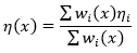
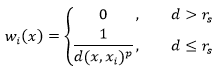
where p is the distance weighting coefficient and rs is the search radius. The distance weighting coefficient defaults to one, but can be adjusted with the use of the HIN file (Weld Surface Mapping). The search radius forces the weighting term wi(x) to zero if the point lies outside the area of interest (when it is very far from the Gauss point). The search radius is determined using the equation:
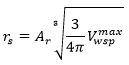
where Vwspmax is the maximum volume of any point on the weld surface as reported in the .ws3 file. Ar represents a multiplier which can be used to widen or narrow the search range. Ar defaults to a value of one, but can be adjusted in the HIN file (Weld Surface Mapping).
View Results
After results have been mapped to the structural model (Home > Mapping > Map Results), switch to the Weld Surfaces visualization (Home > View Results > Weld Surfaces). A contour plot is generated on the structural model that shows the strength reduction factor on the weld surface. For more details on how the strength reduction factors are calculated and used, view the Weld Surface Strengths topic.
Mesh Dependence
The accuracy in mapping weld surfaces to the structural model is dependent on the fidelity of the structural mesh in relation to the Moldflow mesh. Consider the example below for a simple ASTM coupon model of varying structural mesh density.
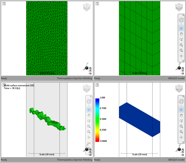
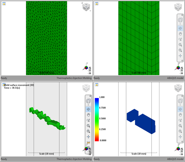
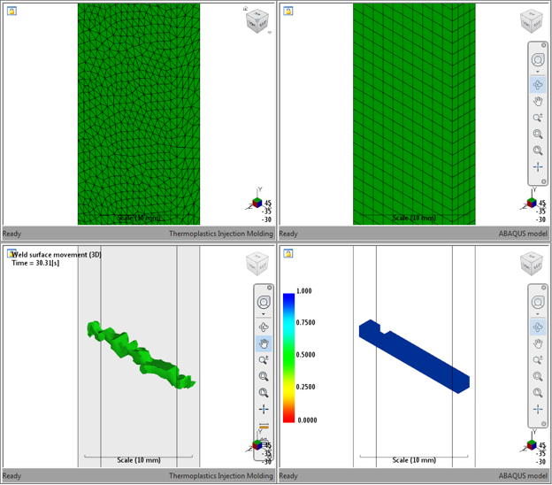
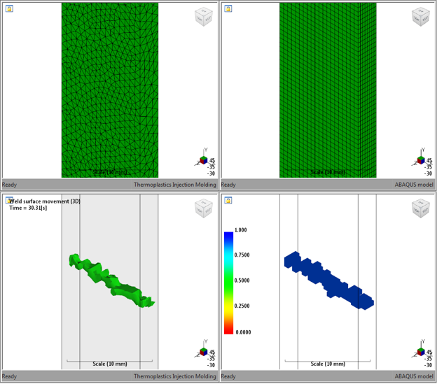
We can clearly see that as the mesh of the structural model is refined, it begins to take on the shape of the weld surface as displayed in the Moldflow model. As a best practice, we recommend your structural mesh density is 1:1 or finer when compared to the Moldflow mesh.