
Learn about the different types of coordinate systems and how you can use them in your modeling process.
World Coordinate System and User Coordinate System
In Advance Steel, the World Coordinate System (WCS) is fixed and the User Coordinate Systems (UCS) can be moved or rotated. The UCS takes precedence in almost all cases, except when a tool specifically refers to the WCS. Advance objects are always created relative to the current coordinate system.
Object Coordinate System
Each Advance object has its own object coordinate system. The X/Y plane of the object coordinate system is perpendicular to the web (parallel to the flange) of a beam or to a plate surface. The Z coordinate points to the top of a beam or represents the default direction for a plate thickness.
If processings or connection objects are created at beams or plates, it is recommended to set a UCS orientation corresponding to a suitable object coordinate system. For example, you can activate an object coordinate system in a plate plane if a contour processing will be created in this plane.
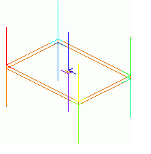
- Rectangular plates have ten object coordinate systems:
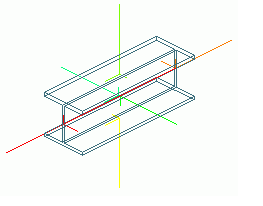
- Beams have six basic object coordinate systems:
Work with the User Coordinate System
You can move the user coordinate system using various methods:
- Move the UCS to a defined point
- Rotate the UCS 90° around the X, Y or Z axis
- Place the UCS at an existing object
- Place the UCS at a curved beam
- Place the UCS at a bisecting line
- Define coordinate system
Each of these methods has a corresponding tool in the Advance Steel Tool Palette, in the UCS category:
 .
.