This section describes how to program the counterbored hole on the rear of the part.
As this toolpath will be machined using the sub-spindle, you first need to create a new Face window.
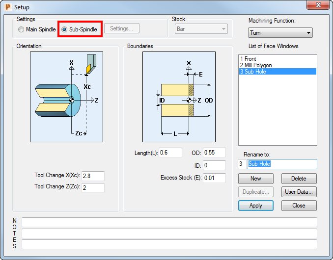
- Select View > Setup and then click New.
- Complete the Setup dialog, as shown, remembering to select Sub-Spindle:
- Select a color for the toolpath from the Color Palette, then click the
New Hole Group button to display the
Hole Group Parameters dialog.

- Complete the dialog as shown, by selecting the
Extract Parameters From Solid option, selecting the hole in the Solids window, and then clicking
Extract.
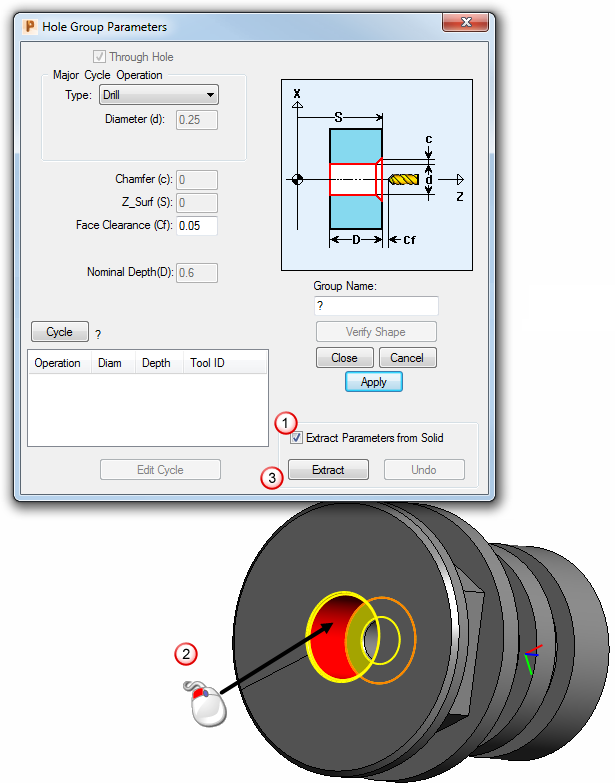
If you are not using a solid model file and so cannot extract the hole values automatically, you need to enter the values shown in the red boxes above directly into the Hole Group Parameters dialog.
- When you click Extract, the Select Cycle dialog is displayed.
- As no suitable cycle already exists, click Add New Cycle to display the Edit Cycle dialog.
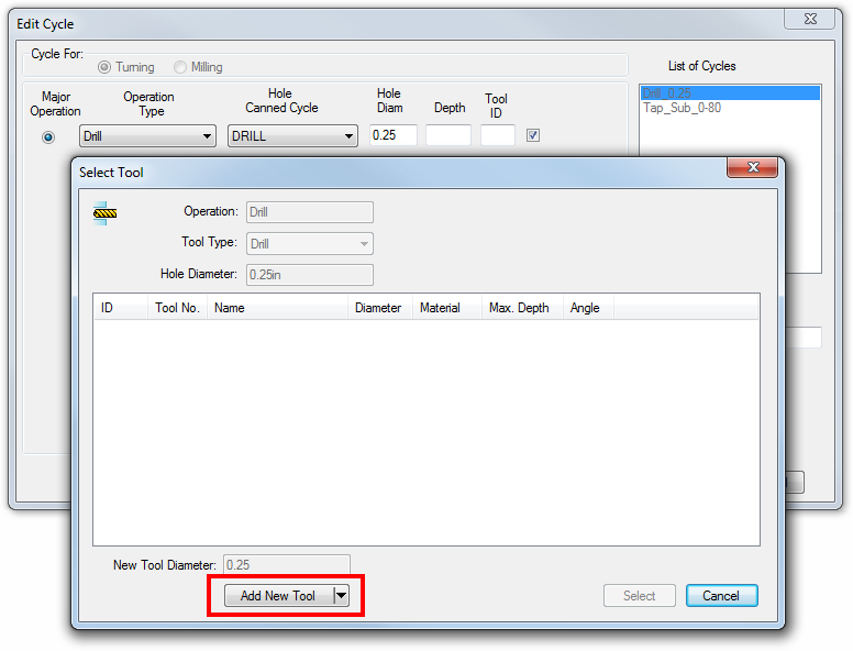
- Click
Select Tools to display the
Select Tool dialog. As no suitable tool exists in the Tools database, click
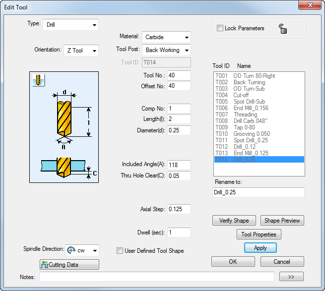
Add New Tool to add a new tool:
- Complete the
Edit Tool dialog as shown, then click
OK.
- Select
OK on the
Edit Cycle dialog to return to the
Hole Group Parameters dialog, then click
Close.
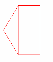
PartMaker displays the drill toolpath in the 2D window: