
This section describes how to program and verify the toolpaths required to machine the part.
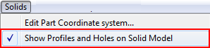
If you are using an imported 3D model, check that the Solids > Show Profiles and Holes on Solid Model option is selected so you will be able to view toolpath profiles on the solid model:
Note: Important programming convention:
When creating geometry, setting up tools, and programming toolpaths in
PartMaker/SwissCAM, it is important to remember that
PartMaker assumes that all work is done moving from right to left in the Z- axis (that is, it assumes that the collet or chuck is always on the left). This convention applies regardless of the physical construction of the machine.
PartMaker makes sure that the NC Program is created in the required coordinate system for your machine during the postprocessing process.