
The flow of water through a network can be regulated by the inclusion of controls. These are links such as valves and pumps. Some controls have a constant effect on the network; others, such as certain types of valves and pumps, may be regulated over a period of time to alter the pressure in the network.
The controls themselves form part of the network. The operational aspects of modelling a water supply system are contained in the control data. This data describes the initial state of the water supply network at the start of a simulation and the policy for controlling the network during the simulation.
The control data and network are separate items within the database. This means that several control data items can be associated with the same network to model variations in control policy; alternatively, the same control data can be associated with more than one network so physical changes in the network can be modelled with the same control policy.
Creating control data
A new, blank control data can be created at any time. Alternatively, control data can be imported into InfoWorks WS Pro.
To create new control data:
- Right-click a model group.
- Select New | Control from the context menu. The New Name - Control dialog is displayed.
- Type a name for the control data and click OK. The new control data will be checked out when created.
Control data can be edited by associating control data with a network, then adding and editing control information for the objects in the network.
Associating control data with a network
- Open a network.
- Drag the control set from the Model Group window and drop it on to the GeoPlan view of the network, or right-click the control set and choose Open.
- The title bar of network view changes when there is control data associated with the network. The network name is on the left, followed by the control data name.
- To disassociate the control data from the network, select Control > Clear control from the Network menu.
-
You can also associate a default control with the network. Right-click the network in the Model Group window and select Associate control.
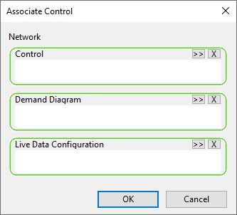
- Drop your chosen default control into the dialog and it will be opened along with the network.
Adding a control
Adding a control is not an explicit action. If a control is associated with the network, the control properties will appear beneath the main properties when you open an object's property sheet.
Tip: Use the
 tool to display an object's property sheet.
Editing a control
Control data can be edited by associating control data with a network, then adding and editing control information for the objects in the associated network.
Alternatively, control data can be edited independently of the network in the Control grid.
The Control grid is displayed when the Window | Grid windows menu is selected and the New control window option is selected:
When you have finished making changes, you must commit the control data to the database. It is not committed when you commit the associated network, unless done via the Commit changes to database button on the File toolbar.
Removing a control
Control data can be deleted for a network object using a tool on the toolbar of the object properties sheet.
- Click the
 (Remove control) icon to remove the control.

Exporting a control
Control data can be exported in an EPANET .INP file (in conjunction with a network) or to a CSV file.
To export control data:
- Select the network (for EPANET format only) or the Control Data set in the Model Group window and right-click.
- Select
Export on the context menu and choose the desired format
- An export dialog file is displayed.
- Select the options you require from the dialog and click OK.
- This will display a standard Save As dialog. Choose where you want to save the files.
Example : Changing pipe controls
For modelling purposes you can close a pipe either permanently or for just part of the simulation without having to change the pipe to a valve.
To close the pipes:
- Right-click the 'Newtown Network' icon and select Open. The network is displayed on the GeoPlan.
-
Open the Newtown Base Control to associate it with the network.
- Zoom in on K400342.K400353.1.
- Using the
button, open the property sheet for this pipe.
The associated control data is shown on the properties sheet.
- Close the pipe permanently:
- In the Pipe Closed Profile section, click the Pipe Closed box to select it.
For a more comprehensive example of how controls can be used in InfoWorks WS Pro, click here.
 Back to main flowchart