User interface tutorial: Create the runner
Click
 (Geometry tab > Properties panel > Defaults), and select
  Runner Properties from the drop-down menu to open the Runner properties dialog.
Select Cold in the Runner type drop-down menu and Circular in the Runner shape drop-down menu.
Enter a Diameter (1) of 4 mm, then click OK.
Click Grid Size from the Defaults drop-down menu on the Properties panel of the Geometry tab.
Set the Grid size to 5 mm and click OK . The grid will not appear at this stage.
Click
 (View tab > Visibility panel > Object Visibility) and deselect Bounding Box.
The bounding box is removed from around the model which will make it easier to create the runner.
Click
 (Geometry tab > Feed System panel > Runner) to open the Create runner dialog.
Rotate and zoom in on the model so that the base of the sprue and the injection location are visible.
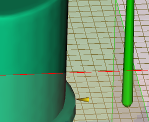
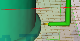
Using the
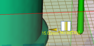
 Select tool (Geometry tab > Selection panel), click at the base of the sprue and drag the pointer away from the sprue, towards the injection location. A thin yellow line that ends with a small yellow sphere appears. This sphere indicates the end of the runner. Since the Snap to grid option in the Create runner dialog is selected, the sphere will jump to the nearest grid intersection.
Click on the illustrated grid intersection.
Right-click in the Graphics panel and select Finish Create Runner from the menu. The runner has been created.