
User interface tutorial: Define the parting plane
Select
 (Home tab > Mold Type panel > Single Cavity).
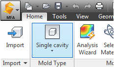
Click
 (Geometry tab > Mold panel > Set Parting Plane) to open the Set parting plane dialog.
The model is displayed with the mold outline and a red line and square grab handles across the model. This line represents the parting plane.
Ensure the Display Grid and Snap to grid check-boxes in the Grid settings box are selected.
Click Bottom then Apply. The parting plane has been automatically set at the bottom of the cavity and an outline of the proposed mold is displayed.
Click Close to close the Set parting plane dialog.