
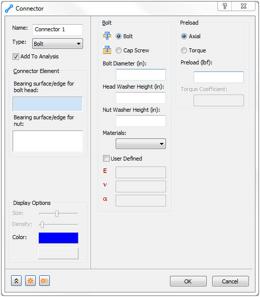
When selecting the Bolt option under Type on the Connector form, the following window comes up:
Bolts will have a visual representation of the bolt. This may or may not exactly replicate what is being analyzed.
- Bolts are an FE representation of stiff bars attaching to the bearing surface(s) and a beam element with the dimensions of the bolt.
- Bolts do not account for contact between the shank and the side wall.
- Stresses in the region of the bearing surface are not very accurate. A more detailed analysis of the joint must be conducted in order to model these stresses better.
- Bolts should not be used with symmetry. The bolt cross section will not accurately represent this.
When the Bolt option is selected, the following sections will become available:
- Add To Analysis: This checkbox automatically puts this bolt connector under Connectors in the current Analysis branch of the tree.
- Display Options: Allows you to change the color of the bolt connector.
-
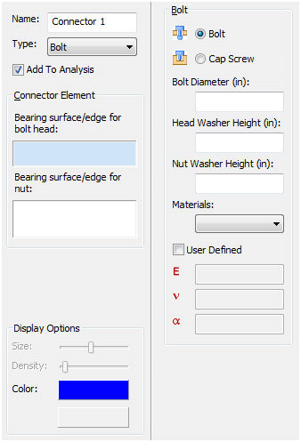
Bolt:
- Bolt: This selects the
Bolt option. A bolt is defined as a bolt with a nut and optional washers.
-
Connector Element: Allows multiple bolt elements to be defined within the current
Connector Name.
- Bearing surface/edge for bolt head: This is a surface or an edge on the head side of the bolt. When selecting a surface, it must represent a bearing type surface.
- Bearing surface/edge for nut: This is a surface or an edge on the nut.
 It is more effective (and typically better modeling practice) to create and use a bearing surface than to use an edge.

Surface
Edge
- Bolt Diameter: This is where you input the diameter of the bolt.
- Head Washer Height: This is where you input the washer height on the bolt head side.
- Nut Washer Height: This is where you input the washer height on the nut side.
- Materials: This is a drop-down list with the available materials created.
- User Defined: This checkbox will allow the definition of critical material properties needed for a bolt (E, nu, alpha (CTE)).
-
Connector Element: Allows multiple bolt elements to be defined within the current
Connector Name.
- Cap Screw: This selects the
Cap Screw option. A cap screw is defined as a bolt that threads into another body with an optional washer.
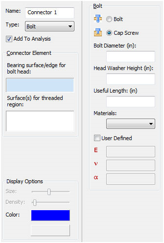
- Connector Element: Allows multiple bolt elements to be defined within the current
Connector Name.
- Bearing surface/edge for bolt head: This is a surface or an edge on the head side of the bolt. When selecting a surface, it must represent a bearing type surface.
- Surface(s) for threaded region: This is a surface that defines the used threaded portion of the cap screw. There are certain instances where more stiffness then is necessary will be generated. Measures should be taken to limit the amount of surface used for threads to only the region where cap screw threads are in contact with the female threads of the body.
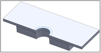
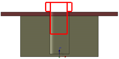
Example: Below is the bolt representation.
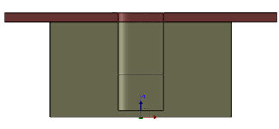
A split line should be made at the end of the bolt to not over stiffen the other body as shown below:
- Bolt Diameter: This is where you input the diameter of the bolt.
- Head Washer Height: This is where you input the washer height on the bolt head side.
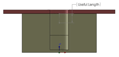
- Useful Length: This is defined as the usable length of thread for a cap screw. By default (when left blank) this is equal to the (diameter of the bolt)/2.
- Materials: This is a drop-down list with the available materials created.
- User Defined: This checkbox will allow the definition of critical material properties needed for a bolt (E, nu, alpha (CTE)).
- Connector Element: Allows multiple bolt elements to be defined within the current
Connector Name.
- Bolt: This selects the
Bolt option. A bolt is defined as a bolt with a nut and optional washers.
-
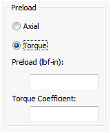
Preload:
- Axial: Allows you to define a simple axial preload for the bolt.
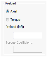
- Torque: Allows you to input the torque value and a torque coefficient to back out a final bolt preload. The equation used to find preload when using the torque option is
Preload = Torque / (Torque Coeff. * Diameter). The torque coefficient is found within literature for losses during preload.
- Axial: Allows you to define a simple axial preload for the bolt.