
To filter the display of the measured points of geometric features in the CAD view, click View tab > View Options panel > Filter Display and select the Geometric Inspection tab.
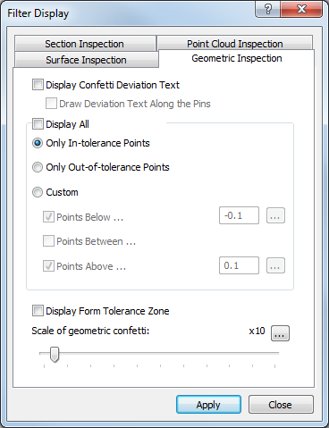
The tab contains the following settings:
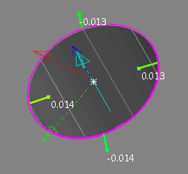
- Display confetti deviation text — Select this check box to show the calculated deviation of each probed point alongside its disc or deviation line.
For example:
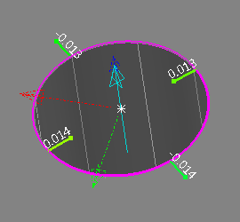
- Draw deviation text along the pins — If the deviation of probed points are displayed as lines or vectors, select this check box to display the calculated deviation along the line or vector.
For example:
- Display all — Select this check box to display all probed points of each geometric feature regardless of the feature's form tolerance. Deselect this check box to choose which points are displayed. Select:
- Only in-tolerance points to display only those points that are within form tolerance.
- Only out-of-tolerance points to display only those points that are out of form tolerance.
- Custom to specify the lower and upper limits of the points to be displayed. Select the Points below check box to display points below the specified lower tolerance limit; select the Points above check box to display points above the specified upper tolerance limit; select the Point between check box to display points between the specified upper and lower tolerance limits.
To base a display limit on the form tolerance of an item, select the item in the inspection sequence, then click
 . The tolerance is halved and displayed in the adjacent box.
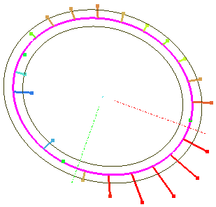
 - Display form tolerance zone — Select this check box to display the limits of each feature's form tolerance in the CAD view.
For example:
- Scale of geometric confetti — Move the slider to change the magnification at which the point indicators and form tolerance zone are displayed. To change the magnification limit, click and enter a new maximum value.
Click Apply to save your changes and display them in the CAD view.