
To filter the display of the measured points of sections in the CAD view, click View tab > View Options panel > Filter Display and select the Section Inspection tab.
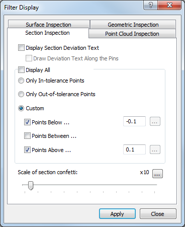
The tab contains the following settings:
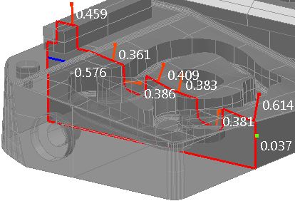
Display section deviation text — Select this check box to show the calculated deviation of each probed point alongside its disc or deviation line.
For example:
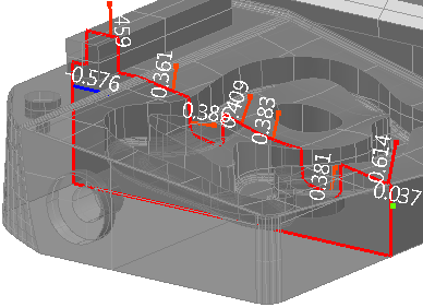
Draw deviation text along the pins — If the deviation of probed points are displayed as lines or vectors, select this check box to display the calculated deviation along the line or vector.
For example:
Display all — Select this check box to display all probed section group points. To limit which points are displayed, deselect the check box, and then select:
- Only in-tolerance points to display only those points that are within form tolerance.
- Only out-of-tolerance points to display only those points that are out of form tolerance.
- Custom to specify the lower and upper limits of the points to be displayed. Select the Points below check box to display points below the specified lower tolerance limit; select the Points above check box to display points above the specified upper tolerance limit; select the Point between check box to display points between the specified upper and lower tolerance limits.
Scale of section confetti — Move the slider to change the magnification at which the deviation indicators are displayed. To change the magnification limit, click  and enter a new maximum value. The slider has no effect when the deviation is displayed as Spot Confetti.
Click Apply to save your changes and display them in the CAD view and the Section view.