
Multiple Transform is an easier method of performing multiple Moves or Rotations of toolpaths.
To display the Multiple Transform dialog, click:
- Curve Editor tab > Edit panel > Transformations > Multiple Transform.
- Toolpath Transform tab > Transform panel > Multiple Transform.
- Pattern Transform tab > Transform panel > Multiple Transform.
- Boundary Transform tab > Transform panel > Multiple Transform.
- Workplane Transform tab > Transform panel > Multiple.
- Edit > Transform on the individual toolpath, boundary, pattern, or workplane context menus.
The orientation of the transform is determined by the principal working plane
 ,
,
 , or
, or
 , set in the
Information toolbar.
, set in the
Information toolbar.
The Rectangular tab contains the following:
 Number of rows — Enter a value or use
 to specify the number of rows.
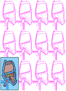
This toolpath transform has 3 rows and 4 columns:
 Distance between rows — Enter the distance between one instance and the next.
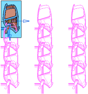
 Rotate axis — Click to rotate the transform by 90
 in a clockwise direction in the principal working plane.
Converts this:
to this:
 Workplane origin — When selected, the active workplane is the origin. If no workplane is active then the global coordinate system is the origin.
 Bounding box origin — When selected, the origin is the centre of the bounding box containing all the entities.
 Move origin — When selected, you can move the origin graphically by dragging or by entering coordinates using
  ,
,  , or
, or  and
and  in the Status bar.
 Distance between columns — Enter the distance between one instance and the next.
 Number of columns — Enter a value or use to specify the number of columns.
This toolpath transform has 3 rows and 4 columns:
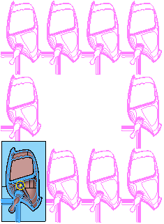
- Hollow box — When selected, places the duplicated toolpaths around the perimeter of the pattern and removes the central ones.
Converts this:
to this:
 Sorting — Select the order to machine the duplicated toolpaths. The start point is always the centre point of the original toolpath.
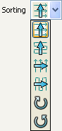
 Along Y, one way in X - creates a toolpath where the duplicated entities are machined in order along the Y direction, one way in X.
 Along Y, two way in X - creates a toolpath where the duplicated entities are machined in order along the Y direction, using two-way machining in X.
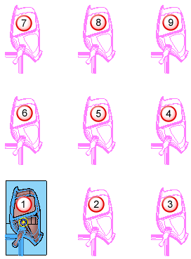
 Along X, one way in Y - creates a toolpath where the duplicated entities are machined in order along the X direction, one way in Y.
 Along X, two way in Y - creates a toolpath where the duplicated entities are machined in order along the X direction, using two-way machining in Y. Clockwise - Click to create a toolpath where the duplicated entities are machined in a clockwise direction.
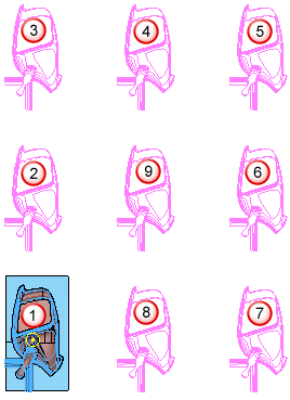
 Anticlockwise — Creates a toolpath where the duplicated entities are machined in an counter-clockwise direction.
For more information, see Rectangular transform example.
For information on the Circular tab, see Multiple Transform - Circular.